I'm developing a bunch of high speed digital electronics (DAC filters etc) and I'm struggling to get a good reading of the high frequency signals. The problem is that the edges are intentionally extremely fast and very square. It seems to be causing a lot of ringing in the scope readings and they are appearing anything but square! Any ideas how I can improve on this? I get the same effect even when measuring the raw clock signal straight out of a single CMOS NAND gate, so it should be pretty clean (and yes, the circuit board design is good - ground planes, bypass caps etc are all as they should be - I'm confident it's a measurement issue not a circuit issue!)
I'm using a Tektronix 500MHz scope (TDS754 so quite old, but pretty good) with a 1GHz passive probe.
I'm using a Tektronix 500MHz scope (TDS754 so quite old, but pretty good) with a 1GHz passive probe.
Hi,
Ringing is common with normal, passive probes (normally only good to 500 MHz). You need the probe and ground probe, just a short spring wire to ground on the probe tip. Your rise time can be calculated to show the bandwidth you need with the scope.
You need an analogue scope, not a DSO. To preserve edges, you need at least 5x the bandwidth, yours is only good to 100 MHz. In truth, if you wanted to see the actual edges clearly without artifacts, you would need a much higher bandwidth scope and probably an active probe with solder-in connections, very short.
So, what is your expected rise time? Use the familiar formula to figure out the bandwidth before slew rate limitations and you have to be beyond that figure. You probably won't like the answer.

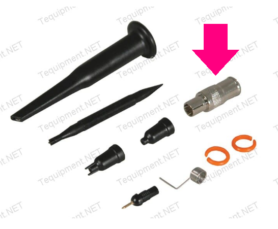
I've had good luck viewing high speed edges, applying the mantra: Reduce Ground Inductance. What has worked quite well for me, is PCB mounted BNC connectors plus scope probe adapters that let me plug the probe straight into the BNC with minimum added ground inductance. Here's an example PCB (link) and a scope probe accessories kit including a BNC-to-probe adapter is shown below.
Another example: (link 2)
Another example: (link 2)
Last edited:
Might try the BNC approach soldered straight on to the board. I have a rise-time of around 0.5ns, so it's generating truly horriffic ringing. I think it's actually in the filter circuit in the scope though. Same frequency signals (67.7376MHz) with much slower edges, such as sticking it through a 74HC logic gate first with a touch of capacitance on the output and the ringing vanishes completely...
I may need a multi-gigahertz scope with an active probe that I really don't want to afford....
I may need a multi-gigahertz scope with an active probe that I really don't want to afford....
N.B. Traces on the board to the next IC input are only around a cm long, so I'm pretty sure I'm not seeing reflections there - that would surely be at a much higher frequency than I'm seeing which is ringing at a few hundred megahertz.
Yes, the spring ground, bottom between the probe tip and probe ID circle clips.
They make pins that solder in and plug into a high speed probe. You want a 50R impedance here (so 1:1). You are still limited by the fact you are using a 500 MHz DSO. You're missing harmonics that will define an edge, and due to that you will see what looks like ringing.
They make pins that solder in and plug into a high speed probe. You want a 50R impedance here (so 1:1). You are still limited by the fact you are using a 500 MHz DSO. You're missing harmonics that will define an edge, and due to that you will see what looks like ringing.
Tek has a good primer on probes: https://download.tek.com/document/ABCs-of-Probes-Primer-60W-6053-17.pdf
The whole section on grounding starting at page 40 is important for high speed probing.
Also, if there is some timing or triggering jitter, that may tend to blur the image some. It may be possible to put the scope into single sweep mode for a cleaner view. Also, some scopes have a some kind of high precision acquisition mode that will oversample to help reduce noise.
In addition, passive probes have tend to have significant capacitance at high frequencies. Scope probe impedance is usually specified as some resistance, say, maybe 1Meg or what ever, in parallel with some capacitance. The capacitance is often the dominant factor at very high frequencies, so maybe useful to take that into account.
There is also a way to make a diy low capacitance probe that can be used up to 1GHz but the DC input impedance is only 1k. Other options for low capacitance probes can be found with a google search.
In fact, I think this is more significant than your recommendation of an analog scope. You will get significantly better results with a DSO of modern calibre than any old analog scope, for fairly obvious reasons. Any decent, modern DSO will have features you can use to your advantage here that you won't find on an analog scope.You are still limited by the fact you are using a 500 MHz DSO. You're missing harmonics that will define an edge, and due to that you will see what looks like ringing.
Try wiggling the probe wiring around and see if its part of the ringing circuit. More often its just the ground lead is too long.N.B. Traces on the board to the next IC input are only around a cm long, so I'm pretty sure I'm not seeing reflections there - that would surely be at a much higher frequency than I'm seeing which is ringing at a few hundred megahertz.
To really see clock risetime well without the probe dominating the measurement, it takes a low capacitance active probe.
Hi HumbleDeer,
Not really. I'm trying to be practical. A high end older analogue scope is far less expensive than a modern digital one would be. New digital scopes have some great features, but mine is about $25K and only 1 GHz bandwidth. The better analogue scopes are really limited by the probe more than anything else. Passive probes are problematic at very high frequencies.
One thing that hasn't been mentioned is the clock frequency and the rise time of the signal. That sets out the parameters you need for the oscilloscope and probe system.
Now that you mention you were specifically looking at purchase price, I can perhaps agree, but that wasn't really in the scope of my comment at first.
That's a really helpful doc. Thanks for the tip. It's describing exactly my problem - a high enough bandwidth scope to measure the ringing caused by a 6" ground clip lead. The traces are exactly what I see.Tek has a good primer on probes: https://download.tek.com/document/ABCs-of-Probes-Primer-60W-6053-17.pdf
The whole section on grounding starting at page 40 is important for high speed probing.
Also, if there is some timing or triggering jitter, that may tend to blur the image some. It may be possible to put the scope into single sweep mode for a cleaner view. Also, some scopes have a some kind of high precision acquisition mode that will oversample to help reduce noise.
In addition, passive probes have tend to have significant capacitance at high frequencies. Scope probe impedance is usually specified as some resistance, say, maybe 1Meg or what ever, in parallel with some capacitance. The capacitance is often the dominant factor at very high frequencies, so maybe useful to take that into account.
There is also a way to make a diy low capacitance probe that can be used up to 1GHz but the DC input impedance is only 1k. Other options for low capacitance probes can be found with a google search.
The drive circuits I'm using are extremely strong, so capacitance shouldn't be a big issue, plus my problems are only 10pF, so not too bad. I think it's the ground lead inductance issue.
Getting off topic a bit.
You've got to be more careful with DSO's as they are a sampling system. They get better, much improved as time goes by. That means for high frequency work you need the new products. But speed is pricey and you've got to look at what you actually need for a measurement. If you don't you will either spend far too much, or have an answer that doesn't reflect reality.
I get the sense APEXHiFi is buying this from his own pocket and not a large corporation with deep pockets. Like me, you've got to be careful what you spend.
Anyway, we need to define what is required / expected before giving a solid answer. But we do know that looking at pulse edges means an extremely high sample rate for a DSO, and a very high analogue frequency response. I do question a passive probe if the frequency is very high.
I want to go further and question what the end goal of this is. Why do you need to see edges without any quantization artifacts or smudging or the likes? Is there something you're expecting to see that will provide answers to your problems, that you aren't seeing right now?
Industry experts in designing these things have done it without as well, and they can probably tell you that you just have to live with it and learn to interpret the edge's shape and ringing and the likes for what it means, not for what it looks like.
Industry experts in designing these things have done it without as well, and they can probably tell you that you just have to live with it and learn to interpret the edge's shape and ringing and the likes for what it means, not for what it looks like.
The BNC adapter Mark suggested is better, but – as others have also said – you can get very good results with the spring clip also shown in the image he provided.

I use those springs a lot when measuring on switch-mode power supplies. They do a wonderful job at reducing the ground inductance, which means the scope sees less ringing. They also reduce pickup of various RF sources, including the SMPS that I'm measuring.
Tom
I use those springs a lot when measuring on switch-mode power supplies. They do a wonderful job at reducing the ground inductance, which means the scope sees less ringing. They also reduce pickup of various RF sources, including the SMPS that I'm measuring.
Tom
My scope handles 2G samples per second per channel, so it's not exactly sluggish, but the edges are so sharp (I'm using 74ALVC and some ECL logic) that it's giving the filter circuits in my poor ageing scope a real headache!
The main thing I'm trying to measure is how clean the edges and signal levels on my digital signals are before I pass them through an analogue filter (delta-sigma DAC), but I think that may be a lost cause...
Even being able to see clean traces on the earlier bits of circuitry so I can confirm timing is as I expect it to be would be helpful. At present it's just a mush of signals with so much ringing on them, particularly when I have all four scope probes connected! I think everything is as it should be, but is it too much to ask for to have perfect magical test equipment that ignores the laws of physics and gives you ideal images of what's there?!
Nice fast edges look great but are an emi nightmare. Be careful what you ask for. . .
To verify that the ringing is not in the source you need to validate with a clean source. At sub nanosecond risetimes it becomes much more difficult to get a valid source.
And while the rise time is interesting if you are looking at logic what matters is when the next stage recognized the change. Severe ringing can cause problems. In high speed logic many interconnections are treated as transmission lines with controlled impedance and often source termination. Signals like HDMI bring a whole host of issues since they have a number of signals that have to have the same delays and are moving at Gigiahertz rates.
I think this includes the Tektronix info, plus it has lots of traces and pictures of how to go about things- https://www.analog.com/media/en/technical-documentation/application-notes/an47fa.pdf
That said, is it really a good idea to have such sharp edges? I'd think it would open up all sorts of emission issues, if one cares about such stuff. "Controlled rise time" seems like something to aim for. (edit- @1audio types faster and is thinking along the same lines!)
That said, is it really a good idea to have such sharp edges? I'd think it would open up all sorts of emission issues, if one cares about such stuff. "Controlled rise time" seems like something to aim for. (edit- @1audio types faster and is thinking along the same lines!)
- Home
- Design & Build
- Equipment & Tools
- How to get a really good measurement of a sharp square wave on a scope?