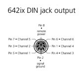
I have an electronic crossover model a/d/s/ 642ix. It has a subwoofer level adjustment feature. But, to enable this feature, it requires to use an additional potentiometer with a DIN cable connected to it. I already have the DIN cable. And I also have the wiring diagram of the pot, shown on attached. The problem is I don’t know how much resistance of the pot to be used. So I’d like to ask how can I find the pot resistance? I have a RLC meter. Also, what will happen if using the wrong pot resistance value? For example, using 10K or 100K pot in place of the correct 50K.
Attachments
If you don't have a schematic for the circuitry that the pot connects to, its hard to say what the effect of a different value pot would have. In that case probably best to use the recommended value. Well, unless perhaps you think the designer made a mistake in calling out the correct pot value?

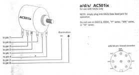
I believe the a/d/s/AC501 subbass level control comes as a module as shown below.

Can I take it that you do not have the module, but want to know what resistance of pot to use in its place?
The problem is I don’t know how much resistance of the pot to be used.
Can I take it that you do not have the module, but want to know what resistance of pot to use in its place?
Last edited:
So I’d like to ask how can I find the pot resistance? I have a RLC meter.
Perhaps you have the pot and simply want to know how to use your RLC meter to measure its resistance?
Please clarify.
Yes, that’s correct.I believe the a/d/s/AC501 subbass level control comes as a module as shown below.
View attachment 1215847
Can I take it that you do not have the module, but want to know what resistance of pot to use in its place?
No, I don’t have a pot.Perhaps you have the pot and simply want to know how to use your RLC meter to measure its resistance?
Please clarify.
Anyway, I was suggested to use the pot that has resistance close to the input impedance of the 642ix. The input impedance published in the manual states it’s about 11k Ohms for RCA inputs or 10-10k Ohms for high-level inputs. Therefore, could it be interpreted that I should use the 10K pot?
Last edited:
May I ask what are the results if using higher resistance i.e. 50k and 100k, please?I'm not familiar with this equipment, but it would appear from what you write that 10K would be a safe bet.
Let me update the progress.
I’ve bought three pots for the experiments; 10KB, 50KA, and 100KA.
The results made me a little bit confused. Firstly, the 100KA gave a little effect on adjustment, it’s likely that the adjustment range was narrow. Secondly, the 50KA gave a widest range. I could hear the largest difference between fully clockwise and counterclockwise with this pot. Finally, the 10KB gave the result similar to the 100KA, it had smaller effect than the 50KA but larger than the 100KA.
Is there any proper method to finding the correct value used? For example, using RLC meter to measure resistance between pin X and pin Y at DIN terminal of the crossover unit.
Regarding a physical method of ascertaining the optimum value of pot in your particular circumstances - I'm afraid not.
Firstly, the 100KA gave a little effect on adjustment, it’s likely that the adjustment range was narrow. Secondly, the 50KA gave a widest range.
Please see post #9. If the pot is not low enough in value, the volume adjustment range will be much reduced.
This is due to the loading of the pot with the heavy load. The 10k pot must not be of the right type, it should be the best.
In fact, the smallest resistance pot value that the circuit source can properly drive will always be the best.
However we cannot be certain of what the source can drive without further information.
But do not compare the volumes at minimum and maximum. This is not how the pot will be used, and is not relevant.
Compare the pots only in the normal range of use, from say "10am to 1pm" like a clock hand.
Last edited:
I’ve bought three pots for the experiments; 10KB, 50KA, and 100KA.
'B' indicates a linear taper, while 'A' indicates an audio (logarithmic) taper.
Perhaps you need a 10 kA? What say you rayma?
The volume control taper will vary with loading of the wiper.
Lower resistance controls will vary their taper less with a given load.
In a particular situation with heavy loading, it's hard to say which taper would work best for you.
Try the 10k again. If there is any doubt, get a linear 10k stereo pot and see if that will work better for you.
Tracking with the linear stereo pot should be better also.
- Home
- Source & Line
- Analog Line Level
- How to find volume resistance to be used?