@Ben Mah yes good point! That also supports my thought that we may actually see the distortion of the Scarlet instead of the amp.
@stef1777 The effect is clear at lower levels (5V) but much smaller at 10V. Again, at lower levels we may see the distortion of the Scarlet while at higher levels the amp distortion might dominate.
Not proven but a reasonable suggestion.
Can you think of a way to find if that is the case?
Jan
@stef1777 The effect is clear at lower levels (5V) but much smaller at 10V. Again, at lower levels we may see the distortion of the Scarlet while at higher levels the amp distortion might dominate.
Not proven but a reasonable suggestion.
Can you think of a way to find if that is the case?
Jan
I tested with another amp with REW's internal oscillator and the two cables. I found the same phenomenon.
To make comparison measurements during development, this is not too much of a problem as long as we keep the same test protocol but you have to choose the right output level for the tests.
If we do the tests at 1W as is often the case, this ultimately does not seem very useful for obtaining real, relatively reliable information. You should choose a stronger level, but which one!
Stef.
Actually what you need is a better soundcard.
You can use a stronger level but then you cannot measure the amp distortion at say 1W, because then the soundcard has too much distortion.
Jan
You can use a stronger level but then you cannot measure the amp distortion at say 1W, because then the soundcard has too much distortion.
Jan
There are products from E1DA as the Cosmos ADCiso but the price is not at all the same. 😡
The current solution is already not bad compared to my old test platform.
The current solution is already not bad compared to my old test platform.
Last edited:

I may have missed something on the past few pages, but if I had a suspect sound card I'd first check its performance by measuring it directly with the Victor's oscillator.
I think I must have this measurement somewhere. I'll look.
Rent an Audio Precision 2700 and do level-by-level comparisons to find when the Scarlett and Co test bench becomes reliable.
To choose the test level, I would tend to say: let's take the average consumption level for HIFI listening at "domestic" sound level. About ten or fifteen Watts but maybe.
In any case, I will now be able to analyze the influence of the input sensitivity value of an amp (internal gain) on the results. Which was the purpose of this upgrade.
Stef.
Can you think of a way to find if that is the case?
Rent an Audio Precision 2700 and do level-by-level comparisons to find when the Scarlett and Co test bench becomes reliable.
To choose the test level, I would tend to say: let's take the average consumption level for HIFI listening at "domestic" sound level. About ten or fifteen Watts but maybe.
In any case, I will now be able to analyze the influence of the input sensitivity value of an amp (internal gain) on the results. Which was the purpose of this upgrade.
Stef.
1W is closer to reality!take the average consumption level for HIFI listening at "domestic" sound level. About ten or fifteen Watts but maybe.
jan
It also depends on the sensitivity of the speakers. I have Dynaudio, they need much more than 1 Watt to know if the amp is on or not. 🙂
It might be better if I change the resistors of the attenuator to give me a -6dB or -10dB. It will be simpler to boost the Scarlett input and still work at 1W in this case.
Stef.
It might be better if I change the resistors of the attenuator to give me a -6dB or -10dB. It will be simpler to boost the Scarlett input and still work at 1W in this case.
Stef.
My understanding of the Focusrite Scarlett is that its best performance is when its input level knob is set at approximately 11 o'clock. That is where I have mine set, and I use an adjustable attenuator to adjust the level to the Focusrite.
https://www.akitika.com/documents/BuildingTheAttenuatorRev4.pdf
I usually aim for about -10 to -16dBFS on the FFT. I get consistent results that are repeatable, and they seem to agree within reason with expected results for the components that I have built.
Attached is the result of the test of my earlier generation Victor oscillator. The oscillator was powered by a linear power supply and the laptop computer was on AC.
Attachments
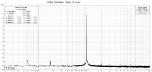
It's an older version, and perhaps the Gen 2 Focusrite was also at its limit.
However for a diyer like me, it is more than good enough as I do not build extremely low distortion audio components.
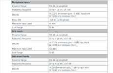
Here are the specifications for the Focusrite Scarlett 2i2 Gen 2. Newer generations have better specifications.
However for a diyer like me, it is more than good enough as I do not build extremely low distortion audio components.
Here are the specifications for the Focusrite Scarlett 2i2 Gen 2. Newer generations have better specifications.
Attachments
Last edited:
Generation 4 no longer has real potentiometers. These are encoder wheels. You can use them but you have to look at the dB cursor on the PC if you want to have precise settings.
The specs have evolved quite a bit and the inputs and outputs are more versatile.
Stef.
The specs have evolved quite a bit and the inputs and outputs are more versatile.
Stef.
Hello,
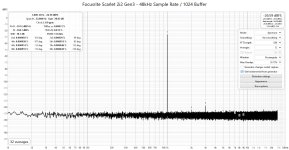
For the owner of old generation Scarlett, I made a TSR cable loopback of the Scarlett 2i2 Gen4 at -1dB (with +6dB of gain at input to have the same level).
Regards,
Stef.
For the owner of old generation Scarlett, I made a TSR cable loopback of the Scarlett 2i2 Gen4 at -1dB (with +6dB of gain at input to have the same level).
Regards,
Stef.
Attachments
Last edited:
I just saw this thread and reading through all 1853 posts seems hard to keep up…
I hope I could make a short question:
Is the Focusrite Scarlet Solo 3rd gen still a good USB inteface for these measurements?
I hope I could make a short question:
Is the Focusrite Scarlet Solo 3rd gen still a good USB inteface for these measurements?
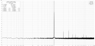
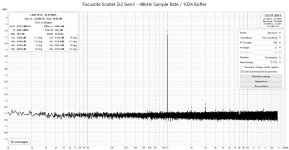
I have the Focusrite Scarlet 2i2 Gen3. Similar to what you are asking about. Here's the loopback I get.
This is with the output monitor knob turned all the way up and the line input knob turned all the way down.
I attached the plots in percent and db.
This is with the output monitor knob turned all the way up and the line input knob turned all the way down.
I attached the plots in percent and db.
Attachments
Your signal is -25dB... so the data is not that impressive. I guess you can get better S/N ratio with higher signal?
I'm still learning how to take readings. Question on this... Here is a plot with the REW my signal generator set to 0 dBFS. Why is the plot showing -12.59dBFS? I have the line input knob set all the way down - I guess I assumed that would indicate no gain on the input, but it seems to be attenuating. Am I interpreting that correctly?
Attachments

Measurement levels are arbitrary, so '-25dB' has no meaning, and is neither impressive or unimpressive. You could use a meter to measure the actual rms volts, and then set the plot units to that (see REW help), but it can be simpler to just assess the dB difference between signal fundamental, and the harmonics, and the noise floor. So in your first plot the 3H is about -110dB (ie. -138+27) lower than fundamental, so not too shabby.
You need to limit the measurement bandwidth to say 20Hz to 20kHz in 'Distortion Settings' menu to avoid very low and very high frequency background noise from being used in the N and THD calculated levels in the distortion panel. Also ensure you have coherent averaging enabled.
Pixworld, any soundcard is good for measurements, especially if you are learning how to use them.
You should be able to get sub PPM THD with Victors and Gen 3 Scarlet. I'll post some pics if I get a chance.
- Home
- Design & Build
- Software Tools
- How to - Distortion Measurements with REW