I am sorry but that's not correct. It is like saying that a car has only two wheels, because the other two are not visible from the sidewalk. You are looking at the OLG of one loop, but there is another one, which you created by connecting the resistor to the output. The extra OLG did not disappear but is now OLG of that new loop, still correcting the output stage errors. Proof:


Last edited:

Yes, but this is an old topic, closed.You forgot about this thread you visited some years ago. https://www.diyaudio.com/community/threads/tmc-or-tpc-my-dilemma-resolved.188133/
By the way this is TMC.
I had forgotten about it.
H
HAYK
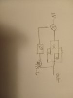
This is what I showed to Minek. The purpose of 2 pole is to get two pole function in the alpha branch of the loop, beta being the feedback. When you put your probe in the second case, you are destroying the alpha function, the probe must be before the beta only as is the first case.. Your probe will artificially see the R2 C4 as high pass because you put the probe in broken loop, in normal function the R2 and C4 have about the same signal hence no high pass. The purpose of 2 pole is to avoid the audio band get integrated, the first feedback RC filters out the audio band to let the integrating capacitor act above the audio frequencies.I am sorry but that's not correct. It is like saying that a car has only two wheels, because the other two are not visible from the sidewalk. You are looking at the OLG of one loop, but there is another one, which you created by connecting the resistor to the output. The extra OLG did not disappear but is now OLG of that new loop, still correcting the output stage errors. Proof:
View attachment 1241539View attachment 1241540
Attachments
Wrt open OLG you usually have a pole at LF - usually a few hundred Hz to a few kHz - set by the VAS stage, and then another pole at HF due to the OPS. The phase and gain margin in this case if you close the feedback loop without any compensation will be inadequate and likely to result in instability.
When you compensate the amp (let’s say standard Miller comp for argument sake), the lower pole gets pushed down in frequency to a few 10’s of Hz and the upper pole gets pushed up in frequency so that it lies below 0 dB - this is called ‘pole splitting’. The phase margin in this case will improve dramatically, making the system stable.
You will have 2 poles in OLG whether you use Miller or TPC.
@HAYK: I don't disagree but rather point to other possibilities.
You refer to the intuitive explanation of how TPC works: R2C4 (on the schematic in my previous post) is a high pass filter that filters out audio frequencies coming to the right end of C3 and thus prevents C3 from providing local feedback to U2 ("integrating"). As a result, the gain provided by U2 at audio frequencies is made available to the global loop - which is the desired result, as extra loop gain (i) corrects the distortion of the output stage and (ii) reduces the difference input signal seen by the front end, helping its linearity. Above the audio band, U2's gain is contained inside the local loop and doesn't extend bandwidth of the global feedback loop.
Obviously TPC is not the only way to add loop gain at audio frequencies. For example, one can ditch the local feedback loop altogether and just load the input stage appropriately:


As seen from the plot, this provides the OLG identical to that of TPC in the audio band, and better phase margin at higher frequencies. The downside is of course the lack of local feedback around U3 and of the associated benefits such as pole splitting.
There are other possibilities. Instead of throwing out loop gain (like I just did above) or applying it only locally to the VAS (as in Miller compensation and in TPC), one can include the output stage in the local feedback loop. At the extreme, if your OPS has enough bandwidth (easy to achieve in a headamp, for example), you can stay with Miller compensation and get the same OLG in the audio band as with TPC:


Here, the gain of U3 at audio frequencies is not made available to the global feedback loop (as it would be with TPC), but still works in the local loop - which now includes the OPS. The price you pay is the need for a wideband output stage and for much better construction, as your feedback loop haw has gain above unity in a wider range of frequencies.
Instead of building a wideband amplifier, one can strike some middle ground and include the OPS into the local feedback loop at audio band but not above it, and that's what TMC does:


At audio frequencies, the gain of U2 (see the schematic in my previous post) is not made available to the global feedback loop, but works in the "middle" loop that includes U2 and the OPS. At higher frequencies, U2's gain is contained inside the shortest local loop around U2. BTW the physics of it doesn't depend on how I plug in the probe in the simulator - the probe simply shows the loop gain in different loops or their combinations, and the results may be difficult to interpret sometimes.
There are other possibilities, one of them implemented in the Omicron:

You refer to the intuitive explanation of how TPC works: R2C4 (on the schematic in my previous post) is a high pass filter that filters out audio frequencies coming to the right end of C3 and thus prevents C3 from providing local feedback to U2 ("integrating"). As a result, the gain provided by U2 at audio frequencies is made available to the global loop - which is the desired result, as extra loop gain (i) corrects the distortion of the output stage and (ii) reduces the difference input signal seen by the front end, helping its linearity. Above the audio band, U2's gain is contained inside the local loop and doesn't extend bandwidth of the global feedback loop.
Obviously TPC is not the only way to add loop gain at audio frequencies. For example, one can ditch the local feedback loop altogether and just load the input stage appropriately:
As seen from the plot, this provides the OLG identical to that of TPC in the audio band, and better phase margin at higher frequencies. The downside is of course the lack of local feedback around U3 and of the associated benefits such as pole splitting.
There are other possibilities. Instead of throwing out loop gain (like I just did above) or applying it only locally to the VAS (as in Miller compensation and in TPC), one can include the output stage in the local feedback loop. At the extreme, if your OPS has enough bandwidth (easy to achieve in a headamp, for example), you can stay with Miller compensation and get the same OLG in the audio band as with TPC:
Here, the gain of U3 at audio frequencies is not made available to the global feedback loop (as it would be with TPC), but still works in the local loop - which now includes the OPS. The price you pay is the need for a wideband output stage and for much better construction, as your feedback loop haw has gain above unity in a wider range of frequencies.
Instead of building a wideband amplifier, one can strike some middle ground and include the OPS into the local feedback loop at audio band but not above it, and that's what TMC does:
At audio frequencies, the gain of U2 (see the schematic in my previous post) is not made available to the global feedback loop, but works in the "middle" loop that includes U2 and the OPS. At higher frequencies, U2's gain is contained inside the shortest local loop around U2. BTW the physics of it doesn't depend on how I plug in the probe in the simulator - the probe simply shows the loop gain in different loops or their combinations, and the results may be difficult to interpret sometimes.
There are other possibilities, one of them implemented in the Omicron:
Last edited:
alexcp, I see that your technical skill is much higher then mine, and I would appreciate your comment on the compensation type I use quite often. The link to the thread is in post #3 .
Damir
Damir
There's also an article by Michael Kiwanuka, "Double Pole Compensation and the Push-Pull Transimpedance Stage in Discrete Audio Frequency Power Amplifiers". He covers the theory and gives examples. Self has it that the two capacitors in series should have the same value as the original Cdom. He also indicates that, if you're adjusting the output stage bias by the minimum distortion method, that the resistor should be disconnected as, with the resistor in circuit, the distortion could well be below the noise floor of the test gear.
Keith
Keith
- Home
- Amplifiers
- Solid State
- How to design Two Pole Compensation, TPC, for a power amplifier. Method?