Hi, everybody,
I am putting together a non-feedback, push pull source follower circuit where DC servo is a needed for decent DC offset at the output. Servo's input is taken from the output of the follower and the output from servo goes to the points where Mosfets are biased by DC voltage.
How to design DC servo with op amp correctly and for best sound ( i.e. no sound).
As I understand a DC servo is kind of feedback circuit.
Must this feedback be negative or positive or maybe delayed regarding input ( in AC terms)?
How much gain should it have? Is less better?
How much bandwidth for servo signal is acceptable?
Regards
Argo
I would think an integrator circuit will serve your purpose.
You may
1. connect the positive input end of an OP to ground.
2. have the MOS out driving one end of 100 k ohm resietor.
3. connect the other end of the 100 kohm resistor to the negative input end of OP
4. connect a 1uF non-polar capacitor between the negative input end and the output pin. The above completes an integrator.
5. connect the output pin to one end of a 10 kohm resistor.
6. connect the other end of the 10 kohm resistor the the MOS driving end.
You may need to lower the value of 10 kohm resistor, depending on the driving source resisance of the MOS.
When the MOS output is positive, the op output will go to negative, and vice versa. This voltage is fedback to pull the DC value back, as long as the feedback voltage is adequately mixed with the MOS driving end.
You may select an OP like OP-27 that has very low offset voltage to get sub-mv offset. General purpos OP can have offset voltage as high as 15 mv.
Hope this helps.
Look at your amplifier circuit. Between the sensing and the feedback point of the DC servo, is it inverting? Then you need a positive feedback DC servo. If it's not inverting, you need a negative feedback DC servo.
To get good sound, select a good opamp and the poles as low as possible. And add a second low-pass after the output of the servo. Basically a DC servo is filtered over-all feedback. To avoid affecting the sound of your amplifier, you need to implement a good sounding and steep filter - not an easy task. All high end audio rules apply here: power supply quality, bypassing, quality of active and passive components...
To get good sound, select a good opamp and the poles as low as possible. And add a second low-pass after the output of the servo. Basically a DC servo is filtered over-all feedback. To avoid affecting the sound of your amplifier, you need to implement a good sounding and steep filter - not an easy task. All high end audio rules apply here: power supply quality, bypassing, quality of active and passive components...
The best you can is to fool around with simulation filesargo said:Hi, everybody,
I am putting together a non-feedback, push pull source follower circuit where DC servo is a needed for decent DC offset at the output. Servo's input is taken from the output of the follower and the output from servo goes to the points where Mosfets are biased by DC voltage.
How to design DC servo with op amp correctly and for best sound ( i.e. no sound).
As I understand a DC servo is kind of feedback circuit.
Must this feedback be negative or positive or maybe delayed regarding input ( in AC terms)?
How much gain should it have? Is less better?
How much bandwidth for servo signal is acceptable?
Look here :http://www.diyaudio.com/forums/showthread.php?postid=455269#post455269
Gain = 1 (when the loop is closed)
Bandwith = 0.1-1 Hz (not too slow)
The adjustment range for the servo should be chosen after how much you need.
If you fool around with my files, please notice that the servo has lower supply voltage than main amp. This means that the servo must be designed so it won't saturate with you have 20 Hz out at max output power.
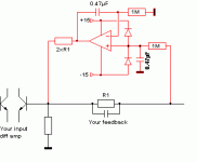
maybe its easier with a schematic, see attached file.
Add the red components.
Be sure your timer of the output L.S. relay is longer than the integration time (maybe 3or4 seconds) because the integrator starts with an unknown value.
If you don’t have +/-15V, make it with +/- Vrail , res, zener and capacitors.
For the ampop, use low offset one like LF411, AD711, or more expensive but not usefull (you dont mind +/-2 mVdc at the output of the amplifier)
If the voltage at the output of the opamp is higher than +or- 10V, choose a lower value or ”2xR1” .
Attachments
Rservo (Your 2xR1) should be at least 10 x R1
You won't probably need these protections diodes and if you put them between the inputs instead.
If both the servo and the main amp are fed from the same voltage you won't probaly need any diods at all, especially if the amp has a transisent free startup.
You won't probably need these protections diodes and if you put them between the inputs instead.
If both the servo and the main amp are fed from the same voltage you won't probaly need any diods at all, especially if the amp has a transisent free startup.
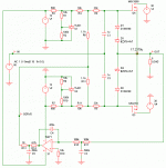
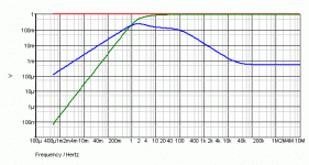
Thank you guys for the hints and especially peranders for the sim files. I now have a better impression how the servo output should look like. The circuit values I had before didn’t give anything near to results peranders has. One thing is that my amp doesn’t have a negative feedback loop. The servo of this amp should inject DC to the output biasing circuitry to balance the DC offset in output. Servo’s performance and also amplifier’s output bandwidth depends also from the biasing circuitry and input capacitor values. I draw up a whole schematic of the amplifier with servo to simulate it. It takes quite a bit fiddling to get the results similar to peranders’s because the situation mentioned above. Ill put the results up to you to evaluate if the sim plots are coming close.
Argo
Argo
Attachments
Don't forget that it doesn't matter if your main amp has feedback or not. The regards the main amp as a gain block only.
Avoid this first filter of the servo. With 3 poles you can get oscillations or get long settling times. One pole is the best but two poles are also OK but you will get small hump in the lowest bass.
Your component values are a bit missmatched but I let you fool around with simulation a bit more. I think you should calculate how you "injection circuit" should look like.
Looks great. The slight hump in the servo curve can be seen to keep the green curve up just a trifle longer, but that's very, very minor.
Should have no negative influence on the sound.
I agree with P-A that you probably can get away with just 2 RC's, cheaper and even more gentle curve. Also, I would increase the resistor from servo output to the amp to get an even better isolation from servo to amp.
What is your offset with this topology (knowing that in real-world it will be different of course)?
Jan Didden
janneman said:Looks great. The slight hump in the servo curve can be seen to keep the green curve up just a trifle longer, but that's very, very minor.
Should have no negative influence on the sound.
I agree with P-A that you probably can get away with just 2 RC's, cheaper and even more gentle curve. Also, I would increase the resistor from servo output to the amp to get an even better isolation from servo to amp.
What is your offset with this topology (knowing that in real-world it will be different of course)?
Jan Didden
Looks great - thats good news. 🙂
What you mean by 2 RC's and having resitor from servo output to the amp (right now I have 2 RCR's one in input of the servo and one in output)?

The simulated offset is 17.2379 microVolts😉
argo said:Hi, everybody,
I am putting together a non-feedback, push pull source follower circuit where DC servo is a needed for decent DC offset at the output. Servo's input is taken from the output of the follower and the output from servo goes to the points where Mosfets are biased by DC voltage.
How to design DC servo with op amp correctly and for best sound ( i.e. no sound).
As I understand a DC servo is kind of feedback circuit.
Must this feedback be negative or positive or maybe delayed regarding input ( in AC terms)?
How much gain should it have? Is less better?
How much bandwidth for servo signal is acceptable?
Regards
Argo
Can you give some details of the source follower. What Z feeds it?
How much offset is there sans servo. Is it a power amp or a
pre amp?
Cheers,
Terry
Re: Re: How to design DC servo?
It's a power amp, biased to 500mA, so about 10W of class A.
I guess the offset without servo would be around couple of hundreds millivolts.
I am planning to feed the follower with the tube front-end with few hundred ohm of output impedance.
Argo
Terry Demol said:
Can you give some details of the source follower. What Z feeds it?
How much offset is there sans servo. Is it a power amp or a
pre amp?
Cheers,
Terry
It's a power amp, biased to 500mA, so about 10W of class A.
I guess the offset without servo would be around couple of hundreds millivolts.
I am planning to feed the follower with the tube front-end with few hundred ohm of output impedance.
Argo
17 uV, he he 😀 but if you use for example AD8610 you will get 70-80 uV without a problem.argo said:
Looks great - thats good news. 🙂
What you mean by 2 RC's and having resitor from servo output to the amp (right now I have 2 RCR's one in input of the servo and one in output)?
The simulated offset is 17.2379 microVolts😉
If you want to make the servo otimimal you must first examine the real circuit and check how much offset you have or will get. When you know than you can choose resistor values.
My recommendation is that you have a more high ohmish bias network. Remember that mosfet's are only like a cap so DC wise you won't need any currents. Increase the values to 100 kohms or more. If you have higher impedance for the bias circuitry the DC servo will get an easier task.
What Jan means is that you should only hav a plain intergrator plus may an output of the intergrator, not a filter in front of also.
I'm totally sure that you can get away with this without any temperature control. Maybe it better to have two current sources as bias and the servo stabilizes it?
- Status
- Not open for further replies.
- Home
- Amplifiers
- Solid State
- How to design DC servo?


