pm me your email, i will send you all that i have saved...Thank you Tony, if you have the rest of information of Patrick Turner I'll appreciate if you can send me a PM or email, thanks.
i did an experiment with the same coil, a 3/4 squared bobbins with more than 1000 turns, the difference between an m6 and H50 is about 3 times more inductance for the same number of turns....
the air gap also played a big role, in a butt joint E to I with minimal gap, you can get 10H, but put a piece of bond paper across the gap and inductance fall to around 3H....
there is no exact way of designing, it is more of an art than science...
but having test equipment helped a lot...
the air gap also played a big role, in a butt joint E to I with minimal gap, you can get 10H, but put a piece of bond paper across the gap and inductance fall to around 3H....
there is no exact way of designing, it is more of an art than science...
but having test equipment helped a lot...
P.M. sent, thank you Tony.pm me your email, i will send you all that i have saved...
Fortunately still exist art, figure the small cartridge bobbins.i did an experiment with the same coil, a 3/4 squared bobbins with more than 1000 turns, the difference between an m6 and H50 is about 3 times more inductance for the same number of turns....
the air gap also played a big role, in a butt joint E to I with minimal gap, you can get 10H, but put a piece of bond paper across the gap and inductance fall to around 3H....
there is no exact way of designing, it is more of an art than science...
but having test equipment helped a lot...
Is the target to make your own choke (eg. existing choke but alter gap, or existing core and wind coil, or ....), or purchase off the shelf from a known catalog ? Is the power transformer, and DC voltage and current requirements known or still very much up in the air? Is there a target DC regulation requirement, or it doesn't really matter?
Note that choke input filter powering for valve gear is perceived as low noise, but caveat emptor regarding why it may have that reputation, as valve diodes are imho a major part of that reputation. If you swap over to ss diodes then you may need to take much more care with noise as the ss diodes are being asked to commutate very rapidly and in a step current manner, which may be a lot more onerous than the more common cap-input filter configuration. You may well have to use fast diodes as well as secondary winding CRC snubbers, as well as a cap bypass before the choke - which may not be trivial given a high secondary winding voltage - and not to mention the very high AC voltage waveform that exists on one end of the choke and could well radiate to sensitive circuitry.
Note that choke input filter powering for valve gear is perceived as low noise, but caveat emptor regarding why it may have that reputation, as valve diodes are imho a major part of that reputation. If you swap over to ss diodes then you may need to take much more care with noise as the ss diodes are being asked to commutate very rapidly and in a step current manner, which may be a lot more onerous than the more common cap-input filter configuration. You may well have to use fast diodes as well as secondary winding CRC snubbers, as well as a cap bypass before the choke - which may not be trivial given a high secondary winding voltage - and not to mention the very high AC voltage waveform that exists on one end of the choke and could well radiate to sensitive circuitry.
Goal is building a pair of audio amplifiers using the chassis and iron of two Hammond AO-68 amplifiers that I already have. What makes these amps interesting is the CT'ed loudspeaker winding that I'll be using for cathode feedback to the finals.
The original PT/PSU features a 350-0-350 Vac secondary winding, a GZ34 rectifier and CRC filtering. In the Hammond design, supply voltage at the 1st filter capacitor is 450 Vdc.
I'm not going to use the GZ34 anymore, but providing SS diodes instead. I'll go for a pair of diodes and a C input filter for plate supply, and another pair with L input filter for the screens, the PI and the cathode followers, to yield Vdc of about 300 V. I still don't have the chokes, but consider to wind them myself, using the iron of transformers that are useless for me otherwise.
May the speed issue be cured by the reverse diode across the rectifier output that I already mentioned?
I'll also toss the 7591 finals and replace them by a pair of 807's in class AB2 PP whose looks I prefer over the rather unimpressive 7591's. Hence 300 Vdc screen supply. OT impedance is 9k->8 ohms.
Due to the SS diodes, the higher plate supply voltage than in the AO-68 original in conjunction with the 807's allows for some more output power, hence headroom, than just 25 watts.
Best regards!
I'm with you on that aim, having just restored a vintage mono PA amp in the same way - it has a 400-0-400V secondary and I changed it to ss diode rectifier into a cap filtered supply for a 515Vdc feed to 807 PP, and a separate ss diode rectifier into a choke input filtered supply for 350Vdc screen. I didn't do anything special for the choke input filter as the two full-wave rectifiers connecting to the same secondary windings take care of each output's commutation. The CT current is the sum of the currents to the cap-input and choke-input supplies, so the pulsed currents for the cap-input filter are combined with the psuedo continuous current to the choke-input filter. I measured 41W max clean, and had the 807's idling at 22W plate dissipation each, and used a 1N4007 in series with a UF4007 for each 'diode' to cover the PIV and to minimise the switching time. I just used a spare junkbox choke with 10H at 21mAdc and 420 ohm DCR. I've included a PT CT fuse, and thought about adding a steering diode to ensure there would be a plate supply feed if there was a screen supply feed but haven't yet added that.
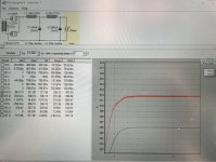
A while back I simulated a choke input power supply for my Tubelab SE so I could have an idea of what off-the-shelf magnetics it would require. I just recently got around to measuring the actual DCR values of the iron I purchased based of those simulations (power transformer secondary and choke DCR) so I could run the simulation again with these values.
Attached below is pictures from the PSUD sim and it would be nice to get some feedback on the results. The second capture is a test of the step response; the ripple looks acceptable but the discharge isn’t as pretty as I’d like. Not sure if it’s something to be fixed.
The Tubelab SE B+ has a target of 300V @ 110mA.
Attachments

a choke is a -6db response and a cap another -6db, so together a -12db response....
imo, the same response can be obtained with an RCRC circuit..but this is more lossy...
imo, the same response can be obtained with an RCRC circuit..but this is more lossy...
Brinkman, what are your concerns in technical terms, and how do you think they would influence your amplifier's performance?
Is the PT effective resistance based on measurement of primary and secondary winding resistances?
Is the PT effective resistance based on measurement of primary and secondary winding resistances?
By PT effective resistance, do you mean multiplying the Primary DCR by the winding ratio K^2? So 370/120 roughly equals 3, 3^2=9, so Primary DCR*9?
My value for secondary DCR was a direct measurement of the transformer I will be using. I just measured the primary DCR (1.2 ohms), so 1.2*9 roughly equals 11 ohms.
This reflected impedance, is it in series with the secondary DCR? If so, my new simulation should have a secondary source impedance of Secondary DCR + Reflected Primary DCR (53+11), so 64 ohms?
As for your other question, one of the tests suggested by SY to check power supply stability was to use a stepped load in the simulation and look for ringing on the B+ when the current steps up. I don’t see ringing but I don’t see a smoothly decreasing voltage either. My gut tells me not to worry about it but my gut has never designed a choke input power supply either.
Hey Brinkman,
for the equivalent resistance referred to primary, you need to know the turns ratio between primary and secondary windings, then square the ration, that will be you constant K. so then equivalent resistance referred to primary becomes Rs + Rp/K
what i do in my psu build is dummy load testing using the actual equivalent resistance of the load it is going to see..
for example, load is 300vdc at 100mA, that is 3k ohms, 30 watts, you will have to use 100 watt of higher resistors as it is going to get very hot...

Yes, in PSUD2 Help section, in the Reference section, then Main Screen, then Design Area, then transformers link, there is a link to the Source impedance calculator, but it is not that helpful as it doesn't explicitly define the secondary resistance for full-wave setup. In the simulation, double clicking on the transformer model, then clicking on the .... box next to ohms will bring up the calculator. The equation used is often shown in rectifier valve datasheets with the V-I curves.
A step load is informative to identify the damped oscillatory response occurring in the LCLC filter - the behaviour is better seen by looking at L2 or C2 current waveforms which indicate a 200ms period damped response - and is a result of the rectifier current conduction levels responding to the changed loading condition. That 5Hz response is well below mains frequency and the audio band, and is damped from the choke DCRs, and is somewhat surreal as it is due to an ideal step in load current. If the oscillatory response was a lot higher in frequency then that may be a cause for concern imho.
A step load is informative to identify the damped oscillatory response occurring in the LCLC filter - the behaviour is better seen by looking at L2 or C2 current waveforms which indicate a 200ms period damped response - and is a result of the rectifier current conduction levels responding to the changed loading condition. That 5Hz response is well below mains frequency and the audio band, and is damped from the choke DCRs, and is somewhat surreal as it is due to an ideal step in load current. If the oscillatory response was a lot higher in frequency then that may be a cause for concern imho.
These were both very helpful replies, so thank you two very much. I learned how to use the […] calculators which I had apparently overlooked.
One area of concern is the Off-load voltage via the calculators made my B+ too high. I’m assuming that as the filaments heat up and the tubes begin conducting that the voltage will settle much closer to the original design target.
one more quick question: is 5% regulation about right for Edcor transformers?
I typically just use the unloaded secondary voltage and effective resistance modelling, but some use the alternative regulation modelling. I'm assuming you have measured the voltage at the secondary winding?
There are many many technical issues relating to simulation accuracy, especially with a choke input filter, so imho I wouldn't get too concerned about absolute accuracy as long as you have measured easier parameters like winding resistances.
There are many many technical issues relating to simulation accuracy, especially with a choke input filter, so imho I wouldn't get too concerned about absolute accuracy as long as you have measured easier parameters like winding resistances.
It's not really about brand. It is a lot about size. 10VA transformers may be wound for over 20%. 500V usually under 3%. At 25,000VA (my house's transformer at the street) they even spec a (industry standard) minimum regulation so a dead-short can't make "infinite" current.is 5% regulation about right for Edcor transformers?
I've even seen values close to 50 % for really small PCB-mounted transformers. I once had to protect voltage regulators with Zener diodes because of the excessive voltage with no load (plain old capacitor input circuit with a 7815 and 7915). Bigger transformers are usually much better, like PRR wrote.
the traffic capacity is more important to me than regulation figures, i seldom use it in my designs...
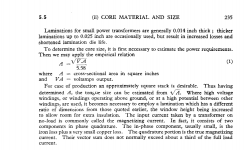
RDH 4 chapter 5 gives an formula for estimating core capacities based on cross section area, VA = Ax5.58^2, where A is area in square inches of core area, VA is volt amperes....http://ds.agavaceae.ru/books/RDH/CHAPTR05.PDF
the procedure is to compute the total of the loads that the secondary of the traffo is going to see, once you have the load calculated, then you look for off shelf traffos that you can buy that satisfied your requirements.....
since i design ang build my own traffos, i can design them, no problem...but i tend to overbuild things traffos...
Attachments
Last edited:
- Home
- Amplifiers
- Power Supplies
- How to design a choke input filter?