Hello everybody, this is my first post here and I hope I am posting it in the right forum.
I am working on a hobby project to build a small audio amplifier. Actually the idea behind the circuit is to build a 0.5W-1W audio amplifier that can be powered from a single 9V battery and have decent audio performance in terms of THD. Keep in mind that I want it to be a discrete design and don't want to use any IC.
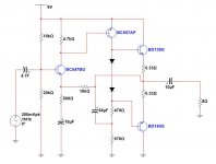
I have built and tested the following circuit with a pure sinusoid input 1KHz and a pure 8 ohm resistive load.
Here is what I found
1. The current in the driver stage (PNP) is between 6-7 mA. This seems to work best for 0.5W output. if reduced, the output distortion appears.
2. The output signal swing is almost 6V pk-pk before it starts to show any signs of distortion. This means that I am getting 0.5W output.
3. i have taken FFT of the output and tried to calculate THD with the above given working conditions, it is less than 1.5% at 1KHz. There are odd harmonics in the output at -60dB less than the fundamentamental freg.
4. It sounds very clean.
Here is my question: The output bias current with no input and no load is approx 12-13mA. As soon as I connect my input sinusoid and resistive load, it shoots up. For a maximum 6 V pk-pk swing it goes up to 120mA. If the output swing is reduced, the DC current also reduces. I don't understand this behaviour. Should not the DC current be constant and not effected by signal and load variation?
Please help me understand this. its killing me. I would like to know if the way im testing the circuit and measuring the DC current is correct and what would be a typical value of bias current for such a circuit?
Thank you all very much in advance for your feedback. Regards,VK
I am working on a hobby project to build a small audio amplifier. Actually the idea behind the circuit is to build a 0.5W-1W audio amplifier that can be powered from a single 9V battery and have decent audio performance in terms of THD. Keep in mind that I want it to be a discrete design and don't want to use any IC.
I have built and tested the following circuit with a pure sinusoid input 1KHz and a pure 8 ohm resistive load.
Here is what I found
1. The current in the driver stage (PNP) is between 6-7 mA. This seems to work best for 0.5W output. if reduced, the output distortion appears.
2. The output signal swing is almost 6V pk-pk before it starts to show any signs of distortion. This means that I am getting 0.5W output.
3. i have taken FFT of the output and tried to calculate THD with the above given working conditions, it is less than 1.5% at 1KHz. There are odd harmonics in the output at -60dB less than the fundamentamental freg.
4. It sounds very clean.
Here is my question: The output bias current with no input and no load is approx 12-13mA. As soon as I connect my input sinusoid and resistive load, it shoots up. For a maximum 6 V pk-pk swing it goes up to 120mA. If the output swing is reduced, the DC current also reduces. I don't understand this behaviour. Should not the DC current be constant and not effected by signal and load variation?
Please help me understand this. its killing me. I would like to know if the way im testing the circuit and measuring the DC current is correct and what would be a typical value of bias current for such a circuit?
Thank you all very much in advance for your feedback. Regards,VK
Attachments
Yes, It should be this way.....Here is my question: The output bias current with no input and no load is approx 12-13mA. As soon as I connect my input sinusoid and resistive load, it shoots up. For a maximum 6 V pk-pk swing it goes up to 120mA. If the output swing is reduced, the DC current also reduces. I don't understand this behaviour. Should not the DC current be constant and not effected by signal and load variation?
This is the work of the output cascade in the AB class.
I suspect your measurement technique is not removing the current across the .33 emitter resistor that goes to the speaker. You can't just put a DVM on volts across the upper emitter resistor and measure bias current that only goes to the lower emitter resistor.
Measure the voltage on the emitter resistor only when the output to speaker is zero, to get idle bias current. Of course I=V/R.
If you had a two channel oscilloscope with Ch A - Ch B function, you could install a .33 resistor in the speaker line and measure voltage across emitter resistor minus voltage cross speaker resistor. That divided by .33 would give you cross current only, the bias current. But I don't have such a scope either. Measuring only silent voltage across upper emitter resistor with a DVM has given me DIY amplifiers that don't burn up output transistors, so I don't worry about it.
BTW if the two diode spreader stack doesn't provide high enough idle current, you can install a third diode then parallel a pot across one or two of them to decrease the voltage to anything you want. Warning, pot wipers oxidize and go open in months or years. This could make the bias current too high. After you measure the right idle current, then measure the pot value and replace it with a fixed resistor.
Last edited:
@indianajo: I am measuring the current by breaking the circuit between the emitter of BD139 and the 0.33 ohm resistor and by placing DMM in current measuring mode. I am using a Fluke meter (I dont remember the number right now) and it has options to show both DC and AC current at the same time. The value 120 mA that I mentioned is the DC current value. That confuses me.
I'll try to measure the speaker current like you said and double check the meter settings and see if I can find a reason.
About the two diodes, I am actually using a vbe multiplier circuit now as it gives me more control and i can adjust the voltage between the base terminals of the output transistors.
@Hennady : ''This is the work of output cascade in AB class'' can you please elaborate. I don't understand your comment.
The current to the speaker goes through the connection of BD139 and emitter resistor also. So when amp is not silent that is not a valid method of measuring bias current, the cross current from BD139 to BD140. The silent reading is the only interesting one.
And the "silent" current reading could be messed up if your amp is ultrasonically oscillating, putting 1 mhz into the speaker. A completely rigorous designer would measure speaker voltage at zero at all frequencies when the amp was "silent". BTW a fluke RMS capable DVM tops out about 7 khz at measuring AC voltage so they will completely miss ultrasonic oscillation. Read the specs on yours. Use an analog VOM or a scope to check for ultrasonics. In the long run analog VOM is cheaper, more reliable. I have several bargain used scopes chock-full-a expired e-caps that worked for a few minutes when I bought them. Waste of money. My 1986 analog VOM works fine; no e-caps.
And the "silent" current reading could be messed up if your amp is ultrasonically oscillating, putting 1 mhz into the speaker. A completely rigorous designer would measure speaker voltage at zero at all frequencies when the amp was "silent". BTW a fluke RMS capable DVM tops out about 7 khz at measuring AC voltage so they will completely miss ultrasonic oscillation. Read the specs on yours. Use an analog VOM or a scope to check for ultrasonics. In the long run analog VOM is cheaper, more reliable. I have several bargain used scopes chock-full-a expired e-caps that worked for a few minutes when I bought them. Waste of money. My 1986 analog VOM works fine; no e-caps.
Last edited:
Only in Class A. Your amplifier is Class B.Herning16 said:Should not the DC current be constant and not effected by signal and load variation?
> output bias current with no input and no load is approx 12-13mA.
As DF96 and others say: in class B the full-output (theoretical 9Vpp) current is much higher, can be computed, the math may be tedious, but 9V supply and 8r load will suck 180mA from supply at full sine output.
If that is what you are getting, all is well. Indeed, voltage-losses limit you to 6Vpp, so we expect 6/9 of 180mA, which is 120mA, which is what you report. It is working as it should.
Note that 6Vpp is 3V peak, which implies 3V/8r= 0.375A or 375mA peak in the load. This can not come from any 7mA-13mA idle. The stage sucks more power as needed. The output stack is series to the power supply so you have 375mA one peak, idle while the other side pulls-down, 187mA if it were a square wave. There is a factor 0.707 for Sine, and 0.9 for complicated reasons. 120mA.
A 9V battery will not sustain 180mA for long. Hardly at all for Sine testing. A little better for speech/music. (Un-clipped.... but a 0.5W amp will tend to be worked into clipping.) We favored 16r loads for OTL pocket radios. If you are messing with guitar-shop 9V battery eliminators, you should be fine.
Last edited:
I see heroic attempts to bias transistors the same way it was done with tubes 50 years ago (by a fixed voltage between control grid and cathode) and laugh... :-(
> fixed voltage
His 2-diode plan has been functional in many-many-many designs over the century.
In a high-strung amp, it wants those diodes nailed to the output devices for tracking. But the devices and power he proposes, and home rooms, not so critical. The output device idle current will rise after a loud passage, but that's not bad. My gut says he won't get into thermal run-away. And if I am wrong, it is $2 of parts. (Actually it would be a $3 battery..... parts have got cheaper than the power for them.)
One loss in the posted plan stands out: 10uFd driving 8 Ohms is cutting bass below 2KHz. A MAJOR cut off full range speech/music, and a small but significant hit on 1KHz testing.
Peter Walked patented much better approach to deal with output transistors, instead of popularizing it in magazines and school books... As the result, the majority does not understand it, nor recognizes it's value...
Given that the OP is struggling to understand the difference between Class A and Class B, arguing about the optimum way to bias the output stage seems somewhat irrelevant to this thread. Could be an interesting discussion, but it belongs in another thread.
Given that the OP is struggling to understand the difference between Class A and Class B, arguing about the optimum way to bias the output stage seems somewhat irrelevant to this thread. Could be an interesting discussion, but it belongs in another thread.
The problem is, BJTs have much higher transconductance than vacuum tubes, and similar bias technique does not work well; there is a thin gap between class C and explosion only due to temperature change. The best way to do voltage bias of output transistors in such topology is to use special Sanken devices that for example Denon uses in their home theater receivers, with output transistors and bias diodes in the same case. Or, to use topologies better suited for BJTs. I can suggest 2 of them in a separate thread, if somebody is interested...
"I can suggest 2 of them in a separate thread, if somebody is interested... "
Please dear Wavebourn !
Please dear Wavebourn !
"I can suggest 2 of them in a separate thread, if somebody is interested... "
Please dear Wavebourn !
I need to refresh some math memory before writing an article. 🙂
Edit: in short:
Class AB has threshold between A and B, right? The same output devices play both roles. Voltage bias is critical and hard to implement.
Approach 1: both devices work in "class A" all the way, from rail to rail, with limited signal level dependent max current, but at some threshold each of them gets capability to deliver higher current.
Approach 2: separate SE amp plays class A role, but at some threshold additional devices get class C role to deliver higher current. No need for voltage bias. This approach was not understood and developed due to Peter Walker's patent with misleading description.
Last edited:
One loss in the posted plan stands out: 10uFd driving 8 Ohms is cutting bass below 2KHz. A MAJOR cut off full range speech/music, and a small but significant hit on 1KHz testing.
+1 increase to at least 1000uF
So it was my mistake thinking that the meter was showing only the bias current. The reading that I am getting is bias current combined with load current, like many of you mentioned. Thank you all!! This discussion is really helpfull to me. I am new beginner with audio amplifiers and learning things by doing it.
About the bias control, unlike the two diodes shown in the schematic, I have changed it to a vbe multiplier. Its easy to control the output bias this way? Maybe there is a better way, please comment or correct me if I am wrong.
About the thermal runaway: It's not an issue in this circuit, so far. I have played around with tying the vbe multiplier transistor and BD139 transistor together and I can see the the effect of negative feedback. But I have a relevant question here: how long should I normally wait for the bias current to stabilize?
If some of you could suggest how to improve the harmonic distortion, please do. Right now for an input sinusoid of 1 KHz, I see odd harmonics at 3KHz, 5KHz, 7KHz, and 9KHz. All these harmonics have approximately same magnitude (-60dB) than the fundamental which is at 0dB. Strangely enough there is a 2nd harmonic aswell at 2KHz with -56dB. Can somebody explain this 🙂
Thanks again for all the comments, I really appreciate this!!!
Are your distortion figures measured or from a simulation ? and what bias current do you actually have flowing in the 0.33 ohm resistors ?
Bias current for a properly implemented and configured Vbe multiplier that is in thermal contact with one of the output transistors should stabilise within 20 seconds or so and track accurately throughout the full range of expected heatsink temperatures, however very few designs come close to this ideal for various reasons. But it can be done 🙂
Bias current for a properly implemented and configured Vbe multiplier that is in thermal contact with one of the output transistors should stabilise within 20 seconds or so and track accurately throughout the full range of expected heatsink temperatures, however very few designs come close to this ideal for various reasons. But it can be done 🙂
I have 10-11 mA bias current in the output stage. I tried increasing the current to 16-18 mA thinking that maybe it will improve the distortion figures but it didn't.
The distortion figures are measured values using FFT on the scope.
Ah okay. I am planing on building a 10-20W amplifier next. So I'll keep that in mind. If you know of any good article/discussion about bias control/thermal tracking, please mention. 🙂
The distortion figures are measured values using FFT on the scope.
Ah okay. I am planing on building a 10-20W amplifier next. So I'll keep that in mind. If you know of any good article/discussion about bias control/thermal tracking, please mention. 🙂
- Status
- Not open for further replies.
- Home
- Amplifiers
- Solid State
- How to control bias current in class AB output stage?