Hello all,
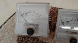
I just saved two vumeters from a deck I saw in the scrap container (Aiwa Ad6500) and I need some advice on how to wire them up in order to use them between my computer line out and amplifier...
Since I am a noob I hope some of you can help me with a few instructions.
Attached you can find the photos (front / back) and the schematic I found over the net.
Thank you
Attachments
You are going to have to do some research, however here are some pointers...
1/ The meters are standard moving coil types and so that means you must rectify the AC (audio) voltage to give DC.
2/ You can use passive rectification using a couple of diodes (germanium types are best because of their low volt drop), however even these result in meters that still need a fair bit of signal to get them to move.
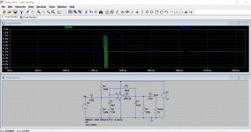
3/ The best method is an active rectifier that overcomes these limitations and this also allows the meter to respond to a fast transient and then 'hold on' a little to the signal so that the needle has to time to move.
This shows a simple opamp stage. Look how the very short duration input signal generates a decaying DC voltage for the meter to work with.
If you want to to use the Aiwa driver then you will have to look at the actual circuit details and not just a board layout.
1/ The meters are standard moving coil types and so that means you must rectify the AC (audio) voltage to give DC.
2/ You can use passive rectification using a couple of diodes (germanium types are best because of their low volt drop), however even these result in meters that still need a fair bit of signal to get them to move.
3/ The best method is an active rectifier that overcomes these limitations and this also allows the meter to respond to a fast transient and then 'hold on' a little to the signal so that the needle has to time to move.
This shows a simple opamp stage. Look how the very short duration input signal generates a decaying DC voltage for the meter to work with.
If you want to to use the Aiwa driver then you will have to look at the actual circuit details and not just a board layout.
Attachments
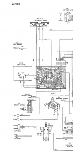
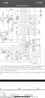
All pertinent data can be doped-out from the service manual:
Aiwa AD-6500 - Manual - Stereo Cassette Deck - HiFi Engine
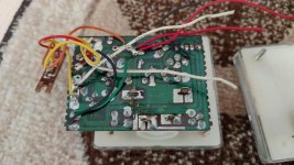
They are DC meters. AIWA put a PCB on back with diodes and buffers. I see you have one; I sure hope you saved the other also. Then all you need is a +20V to +35V DC supply.
The AIWA plan buffered so it would not inject distortion on the Line Out (which is a pot). If you are coming from a PC sound card, these normally have quite powerful (high current low-Z) outputs. Then you can omit the buffer (and power supply). Try that first.
Ge diodes can be had from Small Bear Electronics. (There are many-many on eBay but a lot are NOT true GE, but Schottky which is close or just random sweepings which are probably high-V Silicon.) True 1N34 is equivalent to 1N60 for our purposes. (1N60 is newer so in AIWA's day it seemed better.) In fact any Germanium Small Signal diode will be fine. At The Bear, the 1N3470 ITT, Transitron AN307, and 1N56A Solitron look like good bets.
The 3k trimmer can be a 1k fixed for non-calibrated dancing needle.
Aiwa AD-6500 - Manual - Stereo Cassette Deck - HiFi Engine
They are DC meters. AIWA put a PCB on back with diodes and buffers. I see you have one; I sure hope you saved the other also. Then all you need is a +20V to +35V DC supply.
The AIWA plan buffered so it would not inject distortion on the Line Out (which is a pot). If you are coming from a PC sound card, these normally have quite powerful (high current low-Z) outputs. Then you can omit the buffer (and power supply). Try that first.
Ge diodes can be had from Small Bear Electronics. (There are many-many on eBay but a lot are NOT true GE, but Schottky which is close or just random sweepings which are probably high-V Silicon.) True 1N34 is equivalent to 1N60 for our purposes. (1N60 is newer so in AIWA's day it seemed better.) In fact any Germanium Small Signal diode will be fine. At The Bear, the 1N3470 ITT, Transitron AN307, and 1N56A Solitron look like good bets.
The 3k trimmer can be a 1k fixed for non-calibrated dancing needle.
Attachments
Last edited:
Hello again and thank you all for your answers,
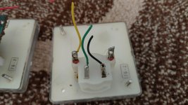
PRR, as long as I remember, it was just one pcb on the back of the left vumeter and from there some wires to the right one.
Hopefully the deck will still be there tomorrow.
I will take a look and get back to you.
Thank you again.
PRR, as long as I remember, it was just one pcb on the back of the left vumeter and from there some wires to the right one.
Hopefully the deck will still be there tomorrow.
I will take a look and get back to you.
Thank you again.
Real VU meters (read: expensive) have a characteristic specification called ballistics, the nature of which allows a recording engineer to see the rate at which a signal is approaching the high end of the range over which the record electronics, tape type, and tape heads can be operated with minimum noise and distortion. Since there may be little or no compression applied to the signal being monitored with a VU meter, the meter's ballistics are more important in the professional setting than in the less critical home recording environment.
In any case, The usage you have in mind needs to supply the meters through an op amp circuit
which includes line isolation buffering. Bandwidth limiting and easily derived adjustment means can be part of the circuit. It will remain a fairly simple design & build, though.
as I recall, the National Semiconductor Handbook for Audio has good examples of metering circuitry.
> specification called ballistics....... needs to supply the meters through an op amp circuit....
When I made money abusing tape, VU ballistics were important. I don't think yulyo is even recording, just entertaining the eye.
When all we had were 300 Ohm lines at +4dBm, meter diode distortion was critical (the VU meter was not possible before mid-1930s improvements in magnet and rectifiers). Now that most audio gear output is low-low impedance, it may not be essential to buffer meter or rectifiers. (However yulyo has a buffer on the salvaged board.)
Last edited:
I have a Technics SU-7300 amp from the 70’s that is faulty. I want to put a new amp inside and use some of the original components including the vu meters. Are they sensitive enough to work off the line in after the volume? My DAC has a 2v SE output and the amp had a sensitivity switch for the VU meters. Could I use the original circuit for the VU meters if I get a bit creative? I thought I might be able to wire in a 10k attenuator where the sensitivity switch is to fine tune it.
Attachments
I would say 'probably not' tbh. Not 'as is' anyway.
The circuit is relatively insensitive being just a passive design. Note the diodes which are OA germanium types, chosen for their low forward voltage.
Another problem is the input impedance of the circuit is a bit low to hang off a low distortion line level source even if it could drive it otherwise.
Hanging it on the wiper of the volume control is out of the question I'm afraid.
Having said that, you could easily rig up a single dual opamp to drive them (with gain if needed) and you could feed that from the volume control directly. That's easy to do.
OK ") Remember fidelity and noise isn't of any importance here so you can go really high on things like input impedance. A FET opamp like a TL072 would be happy with 10 meg input resistance and this would give essentially no loading to a volume control wiper if AC coupled, or if the control is ground referenced (as most are) then just connect directly to the wiper.
Remember fidelity and noise isn't of any importance here so you can go really high on things like input impedance. A FET opamp like a TL072 would be happy with 10 meg input resistance and this would give essentially no loading to a volume control wiper if AC coupled, or if the control is ground referenced (as most are) then just connect directly to the wiper.
Remember fidelity and noise isn't of any importance here so you can go really high on things like input impedance. A FET opamp like a TL072 would be happy with 10 meg input resistance and this would give essentially no loading to a volume control wiper if AC coupled, or if the control is ground referenced (as most are) then just connect directly to the wiper.You are going to have to do some research, however here are some pointers...
This shows a simple opamp stage. Look how the very short duration input signal generates a decaying DC voltage for the meter to work with.
Best group of guys ever on this forum !!!
Mooly, things have changed a bit. I now have an Audio Inerface that has a balanced output driving my TPA3255. It does have a headphone jack that is connected to the volume but I don’t think it will drive the VU meter as it is 260mW and 1ohm. The amp is about 120w 8ohms and the original amp was 41w.
Would my best option for connecting be to speaker outputs? Would I need to put an attenuator in the circuit and where? Do I ground the circuit to the case?
Would my best option for connecting be to speaker outputs? Would I need to put an attenuator in the circuit and where? Do I ground the circuit to the case?
Last edited:
As long as you have enough driving voltage it will work. If you connect it to a bridged speaker output then you must either connect the circuit across the two terminals, probably with a series resistive attenuator or connect it from one terminal (either + or -) to ground. If you connect to ground you must AC couple the circuit because a bridged amp will have both terminals at some DC voltage above ground.
Also the two meter circuits (L and R) must be electrically separated if you connect across the terminals. They can not share a common 'ground' between them.
The attenuator would go in series with the 330 ohm.
Across the terminals is probably the best option actually because wiring to ground would create a large initial deflection of the meter as the coupling caps charge.
You just need to experiment a bit with it.
- Status
- This old topic is closed. If you want to reopen this topic, contact a moderator using the "Report Post" button.
- Home
- Design & Build
- Parts
- How to connect vu meters