Hello,
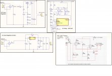
I am trying to build my first tube preamp prototype based on RCA 12AU7 line amplifier drawing in the Tube Receiving manual.
I am trying to figure out how to handle the grounding for the HV/LV linear regulator supplied 12AU7 preamp. Anyone know best practice? Are the grounds referenced to Chassis earth ground or am I to keep them isolated?
Attachments
Looking at your schematics one thing comes to mind, it's complex where it doesn't need to be. For instance you don't really need a soft/delayed start on a preamp, some here on the forum would say no soft starts needed at all. Everyone has their own ideas, but still, I'd ditch the soft start. The beauty of valves/tube amplifier's to my mind is their simplicity, just a thought.
Regarding your question grounding is a complex subject, but for a good article on the subject is here - http://www.valvewizard.co.uk/Grounding.html I've read loads of papers and books on valve amplification, you can't beat Merlins site for easy to understand info.
Lastly a simple rule of thumb re grounding is the highest current draw circuits go nearest your power supply, with your signal ground last, and your signal ground is grounded in one place only on the chassis. Give some thought to your layout, build the preamp, but be prepared to make changes, therefore don't secure grounds etc too securely, it's easier to then make any changes. There is a school of thought that all connections should be physically 100% secure before soldering, EG wrapping wire round several times on valve bases etc, this is a fecking pain in the artichoke if you have to do any subsequent work or alterations and isn't needed. Tektronix built their 500 series valve scopes with solder joints only, most of these are still running 60 years later.
Andy.
The chassis is not normally used for the audio common (or ground) except in musicians' equipment.
However, the audio ground is usually referenced to the chassis by an impedance,
such as a small value resistor and/or power diodes, for safety.
But a direct connection to the chassis can cause hum and noise in some cases.
Always connect the chassis to the IEC safety ground for safety, regardless.
Are you using pcbs, or point to point wiring?
Always return the ground lead of the capacitor that is just after the rectifier
directly back to the rectifier or to the center tap lead. This is a noisy connection.
Then take that return point out to the downstream supply circuitry.
Last edited:
Safety first, always assume that a barefooted person, standing on a damp basement floor, holding a nearby sink faucet, in a towel just out of the shower, is the person operating your amp. So any metal parts people can touch need to be directly bonded to your house. Your metal chassis always needs to be bonded tightly/directly to your IEC ground right at the entrance, this is what makes your chassis not be an electrocution hazard.
After safety is in place, it is ok to lift your circuit ground (audio ground) up using the diode/resistor/capacitor circuit rayma mentioned. This safely references your audio ground to the safety (house) ground but still keeps them separated by 1.4 volts at the same time (which detaches mains hum). So it makes your audio (circuit) ground both safe and isolated, if there is leakage +/- 1.4v, IOW something bad is happening, then this lifted ground will connect itself to the safety ground when you need it to at a safe 1.4 volt trigger point.
This Tube Cad article explains how this circuit works, scroll down to the blurb that explains how this circuit works. In the second picture the word "Chassis Ground" should really say "circuit ground".
The first picture indicates how to use the second picture.

Here is that little tubecad audio ground circuit and explanation
https://www.tubecad.com/2014/03/blog0282.htm

To further reduce current noise, the current loop around the diodes and the first capacitor needs to be tight so star ground that (C1 negative), from that star run a single wire to your pi filter input chain (usually a resistor or choke), then run a single wire from your pi filter output chain end to your lifted "circuit ground". This helps isolate the violent diode/C1 loop.
After safety is in place, it is ok to lift your circuit ground (audio ground) up using the diode/resistor/capacitor circuit rayma mentioned. This safely references your audio ground to the safety (house) ground but still keeps them separated by 1.4 volts at the same time (which detaches mains hum). So it makes your audio (circuit) ground both safe and isolated, if there is leakage +/- 1.4v, IOW something bad is happening, then this lifted ground will connect itself to the safety ground when you need it to at a safe 1.4 volt trigger point.
This Tube Cad article explains how this circuit works, scroll down to the blurb that explains how this circuit works. In the second picture the word "Chassis Ground" should really say "circuit ground".
The first picture indicates how to use the second picture.
Here is that little tubecad audio ground circuit and explanation
https://www.tubecad.com/2014/03/blog0282.htm
To further reduce current noise, the current loop around the diodes and the first capacitor needs to be tight so star ground that (C1 negative), from that star run a single wire to your pi filter input chain (usually a resistor or choke), then run a single wire from your pi filter output chain end to your lifted "circuit ground". This helps isolate the violent diode/C1 loop.
Last edited:

Hi Guys -- Thank you for the replies.
Thanks!
Jeff
Diabolical Artificer - I am just testing ideas. I wanted to test and tune the HV delay circuit in a small preamp circuit. I know that applying HV when the tubes are cold is generally bad practice. Albeit, many designs do not use it for small signal tubes and some do (Audio Research D70). I understand your point completely. I do not have any measurement data to bring to the table to argue that soft-starting generally increases the life of a tube.
rayma - "Are you using pcbs" yes, each block was planned to be PCB but I plan to intergrate it to one PCB which makes the ground routes a little more confusing.
Windcrest77 - Thank you for the tubecad reference. I think I definitely need to read that!
Thanks!
Jeff