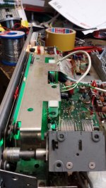
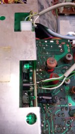
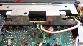
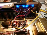
You could also do it very neatly with a small chassis mount bridge rectifier and simply solder the reservoir cap direct to the bridge. The series resistors could be included in the wiring to the LED's and covered in heat-shrink.
Hmmmmm, I'm taking this all in! Now it looks like I'm going to have to take out all the 510-ohm resistors for 12v on each LED and wire them in series across C03 23v. That seems to be the simplest way to go? Once they are wired up I can try different resistors to adjust the brightness. If it by chance causes any problem with the operation of the tuner I can do a chassis-mounted bridge rectifier with a 1000uf cap then but from what I can gather so far the C03 power source and LEDs in series is the way to go. But Hang on! Can I just run all 6 positive wires to C03 positive and the other six to C03 negative? 😀
Last edited:
You need to appreciate the difference between series and parallel connections and how it relates to current draw.
Lets say you have six LED's, and each one needs say 20 milliamps. If you have a 20 volt rail available then each series resistor need to be approx 20 volts less the LED volt drop, so lets say 17.5 volts, divided by 0.020 which is 875 ohms.
Each LED will then draw 20 milliamps giving a total draw of 0.02 multiplied by six. 120 ma in total. Quite a lot.
If you wire them in series we get 20 volts less six 'forward volt drops' of 2.5 volts. So that is 20-(6*2.5) which is 5 volts. We now have only 5 volts to 'lose' across a resistor and that calculates out at 250 ohm.
Both scenarioes light the LED's equally, however one draws 120 milliamps and the other just 20 milliamps.
The BIG downside to the second option is that there is little 'compliance'. A relatively small change in the unregulated 20 volts would see the LED current change significantly.
One possible answer is to split the LED's into two chains. That would give 40 ma total draw.
Or use the dedicated high current winding that the bulbs used which is still my preferred option.
I've read up on this but putting it into practice is another thing, I'm just not confident because I know there is always something I hadn't considered. So if I connect up to the original light windings I would have one with 6.6vac and the other one is 19vac. They are 5.7vac and 17vac on the schematic. How would I wire up the bridge and cap rectifier? Would I go off the 5.7vac or the 17vac or both?, I don't know what a chassis mount bridge rectifier would look like? Is it insulated and bolted on? I'm itching to start on this. lol
Small plastic bridges with a hole for mounting:


Fix the bridge to the chassis, wire the transformer to the bridge using the existing AC feed to the lamps, wire the reservoir cap neatly across the other two terminals of the bridge.
That will give you an 8 to 9 volt DC supply with plenty of current availability and because there is no detriment to the main tuner supply you can run the LED's as you want using a separate resistor to feed each one.
This makes it so easy! Good on you Mooly, you've done it again thanks heaps and thanks again for your patience.
Nearly two years ago I did something similar at a DUAL KA 60 radio/amplifier/record changer console. I replaced the two dial lighting bulbs and the meter lighting by two strings of two green high efficiency LED's and fed them from a small bridge and 'lytic. ANd yes, the stereo indicator lamp was also replaced by two LED's.
Best regards!
Best regards!
Attachments
re post 22.
Also, consider the power dissipation of the resistor -
(5 x 0.020) = 0.1 W
a 0.25W resistor would be adequate here.
vs
(17.5 x 0.020) = 6 resistors @ 0.35W each = 2.1W total.
You would need 0.5W resistors here.
Also, you will sometimes come across parallel LEDs with shared resistor.
This can and does result in unequal current sharing and (considering the cheapness of resistors) best avoided.
VW high-level brake lights, I'm talking to you!
Nearly two years ago I did something similar at a DUAL KA 60 radio/amplifier/record changer console. I replaced the two dial lighting bulbs and the meter lighting by two strings of two green high efficiency LED's and fed them from a small bridge and 'lytic. ANd yes, the stereo indicator lamp was also replaced by two LED's.
Best regards!
That green dial is a good look and adds to the vintage style too.
re post 22.
Also, consider the power dissipation of the resistor -
(5 x 0.020) = 0.1 W
a 0.25W resistor would be adequate here.
vs
(17.5 x 0.020) = 6 resistors @ 0.35W each = 2.1W total.
You would need 0.5W resistors here.
Also, you will sometimes come across parallel LEDs with shared resistor.
This can and does result in unequal current sharing and (considering the cheapness of resistors) best avoided.
VW high-level brake lights, I'm talking to you!
Good point to mention the resistor dissipation in that 20 volt example.
That green dial is a good look and adds to the vintage style too.
The original bulbs were painted in green, too. They were 12 V 0.1 A, not unobtainium, but I hadn't them handy. So I decided to opt for LED's instead.
Best regards!
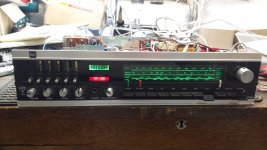
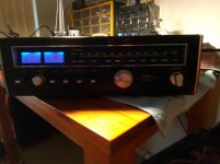
Do you plan to illuminate the dial in blue also? Would fit perfectly, imho!Finally got it done and it looks great! It won't look as good on a photo for some reason? But I'm happy with it all the same. 😀
Best regards!
Do you plan to illuminate the dial in blue also? Would fit perfectly, imho!
Best regards!
The dial is illuminated with two blue LEDs it just doesn't show up in the photo?
Little incandescent bulbs with two wires coming out the glass are easily available . They are perfect to run in series and you can choose between 6,12,or 24v . Once in series they last for ever and are the perfect match for an old gear . I use 2,12v , to run on the 6v ac and the light is enough and current draw very low . The light is so warm and pleasing to look at !
When i use leds to make a little lens i use a metacrylate screw with the end polished to get a more diffused light as leds are always blessing in the dark.
When i use leds to make a little lens i use a metacrylate screw with the end polished to get a more diffused light as leds are always blessing in the dark.
Finally got it done and it looks great! It won't look as good on a photo for some reason? But I'm happy with it all the same. 😀
Excellent

Glad you got it working.
I would be looking at an available constant current driver circuit for these, and bag the resistors if I were going about it.
I would be looking at an available constant current driver circuit for these, and bag the resistors if I were going about it.
- Status
- Not open for further replies.
- Home
- Design & Build
- Construction Tips
- How to change over to LED lights.
