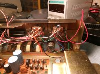
I had some blown dial lights in my Sansui TU-7700 tuner so I decided to change them over to blue LEDs while I was at it so I ordered some 3mm and 5mm blue LEDs with 510-ohm resistors in series for 12v. My question is, can I run a wire from the 12v rail and connect 6 LEDs to it? I'm thinking about the 2v drop for one LED x 6 = 12v? I know the basics of LEDs I just need to know how and where to connect them up properly without them affecting the tuner's performance? The schematic voltages are ac! 😀
Attachments
Blue LEDs typically have a voltage drop of about 3 volts, so six of the in series would require at least 18 volts, probably a little more just to get a useful amount of current through them. The only way to power them from a 12 volt supply would be to parallel two groups of three LEDs in series, each group having its own current limiting resistor, probably something on the order of 150 ohms to 470 ohms depending on how bright you want them.
Like this:
Mike
Like this:
Mike
Last edited:
There is a 19vac connection available, could I hook them up to that? Remember I need three sets of two LEDs, I already have one set of two LEDs running happily in parallel off the 19vac but they both have resistors in them so I'll take one out. Thanks for replying its appreciated.Blue LEDs typically have a voltage drop of about 3 volts, so six of the in series would require at least 18 volts, probably a little more just to get a useful amount of current through them. The only way to power them from a 12 volt supply would be to parallel two groups of three LEDs in series, each group having its own current limiting resistor, probably something on the order of 150 ohms to 470 ohms depending on how bright you want them.
Mike
Last edited:
LED's are current rather than voltage driven and they draw very little.
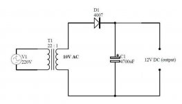
I would connect them as Michael shows or even better, convert that extra winding to a DC supply. You only need one diode and one 470 or 1000uF cap.
If you are running them off AC then you have two problems. One is that they will almost certainly see a reverse bias voltage exceeding their design limits on each blocked half cycle and secondly, they will visibly flicker if you look at them out of the corner of your eye.
Yes, I can see the flicker. Do you mean the supposed 17vac according to the schematic that measures 19vac? Which way across the AC does the diode and cap go? Cathode to negative and anode to positive?
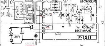
I was actually thinking of using the winding that supplies the bulbs but seeing as the LED's will draw so little current anyway you could try connecting them across cap C03 and leave the other winding unused.
There are lots of options for anything like this. If you did use the other winding then it would be configured like this.
There are lots of options for anything like this. If you did use the other winding then it would be configured like this.
Attachments
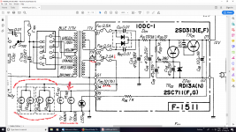
The voltage here in Australia is 240v just in case it makes much difference in the voltage, would the wires come off Fuse 03 and G1? On the other hand, if 6 blue LEDs in 2 sets of 3 in series doesn't draw much current on C03 then that would be the easiest option really so if that is correct I'm going with that!
The mains voltage variations won't make much difference. The transformer voltage on that winding will rise when the heavy load of the bulbs is removed, perhaps as much as 10% but again, it makes little difference.
What you need to do is is first of all wire the LED's and their resistor into a test circuit so that you can determine exactly how bright you want them and how much voltage they drop.
From that you can come up with a plan such as having two LED's or three in each chain.
What you need to do is is first of all wire the LED's and their resistor into a test circuit so that you can determine exactly how bright you want them and how much voltage they drop.
From that you can come up with a plan such as having two LED's or three in each chain.
Attachments
Ok Mooly, sounds like a plan! I'll start doing some tests with the LEDs tonight and see what I can come up with! Thanks, heaps and Michael Bean too, thanks mate!
I'd connect them all in series and feed them off C03 through a suitable series resistor.
Best regards!
Best regards!
Unless the power source is a constant current source you always need a resistor in series with the LED's.
I'd connect them all in series and feed them off C03 through a suitable series resistor.
Best regards!
I couldn't find C03 so I recapped the power board and found it printed underneath a cap. The consensus is that I connect across C03 and use two sets in parallel of three LEDs in series. 😀
I'd first measure the DC voltage over C03. About 23 V can be expected. This is well enough to feed all six blue LED's in series and drop the superfluous voltage with a resistor.
Best regards!
Best regards!
I'd first measure the DC voltage over C03. About 23 V can be expected. This is well enough to feed all six blue LED's in series and drop the superfluous voltage with a resistor.
Best regards!
Spot on, it reads 22.84v across C03! Do you mean I won't need to split the LEDs into two sets of three and I can put all 6 in series with one resistor?
I'd connect them all in series and feed them off C03 through a suitable series resistor.
Best regards!
That's what I thought you said? I was just making sure before I dived into it. Thanks, mate and everyone who has helped me out here with their ideas and suggestions, I have another TU-5500 to do after this one so I'm right up to speed now thanks to you guys. 😀
My suggestion is to build a small PS board run off the original 6V winding.
Rectify the AC, filter it, and a suitable resistor in series with the LED string.
Simple, doesn't interfere with the B+ load, and I've done it many times.
Rectify the AC, filter it, and a suitable resistor in series with the LED string.
Simple, doesn't interfere with the B+ load, and I've done it many times.
Will work, too, for sure, but at much higher effort.
Best fegards!
Oh please, a simple little tiny board, a 20 minute job is all.

Personally, I would not advise using LED's in series. If one screws up in the string, the whole string is compromised. Find a good d.c. supply and use resistors for each LED..
- Status
- Not open for further replies.
- Home
- Design & Build
- Construction Tips
- How to change over to LED lights.