now how good of a plan would it be, to twis all of the wires off the amplifier board? such as the wires to the powersupply all twisted together, and the 2 to the speaker?
keep each channel separate, twisting 2 +/- or +/g wires from the same channel is a good idea, but twisting all the wires together from both channels will induce crosstalk
But shouldn't the + and - be drawing everything opposite of the ground? Making it all cancel? Obviously being separate from the speaker and input.
And yes, I plan on the channels being separate from eachother, but I'm talking about the + - and ground from one channel by itself
And yes, I plan on the channels being separate from eachother, but I'm talking about the + - and ground from one channel by itself
I'm there.........!
6L6...... ran my final amp module checks this evening at full bias. Info posted on my "build thread", FYI.....
How is your F5 build progressing? You must be about there, too!
Ken
6L6...... ran my final amp module checks this evening at full bias. Info posted on my "build thread", FYI.....
How is your F5 build progressing? You must be about there, too!
Ken
I just read your thread entry -- congratulations! 🙂
I need to complete a bit of modification to the case. (the way the bottom connects to the rest of the structure is inadequate, and it must be reinforced) And complete the grounding.
Then it's on to firing it up and tuning for minimum smoke!!
I need to complete a bit of modification to the case. (the way the bottom connects to the rest of the structure is inadequate, and it must be reinforced) And complete the grounding.
Then it's on to firing it up and tuning for minimum smoke!!
Smoke
6L6,
When dealing in high Class A power consumption.....
We don't call it "smoke".......we call it "aroma therapy".......
Best of luck..... My trip's been delayed until Saturday, but I should be back in about 3-4 days after that.
Keep me posted!
Ken
6L6,
When dealing in high Class A power consumption.....
We don't call it "smoke".......we call it "aroma therapy".......
Best of luck..... My trip's been delayed until Saturday, but I should be back in about 3-4 days after that.
Keep me posted!
Ken
A little bit of mechanical before firing it up...
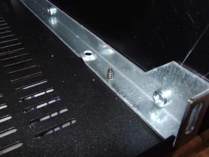
This is a photo of the interface that is supposed to hold the entire bottom plate to the chassis. 4 sheetmetal screws. 😕 Really? Who thought this was good idea? Anyway, It needs to be addressed...
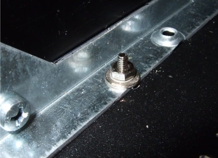
Washers and real hardware to the rescue! This is the new interior hardware,
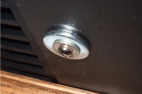
And this is the exterior. I have a bunch of the fender washers, so it seemed like a good place to use one. This should hold the 12lb (5.4kg) transformer and the rest of the PSU securely to the chassis.
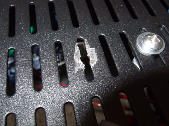
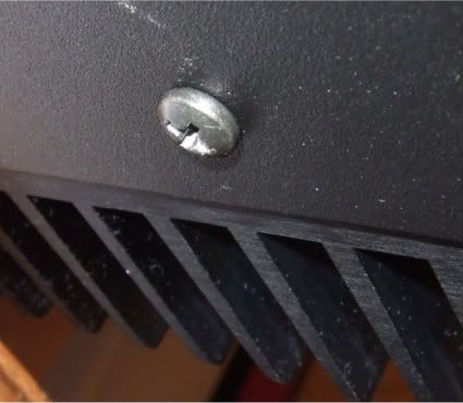
Lastly I needed to make the chassis safety earth. So I scraped the paint (top and bottom) until bare metal was showing, and secure a bolt with star washer also on both sides. This way the star washer digs into the bare metal, making a good connection.
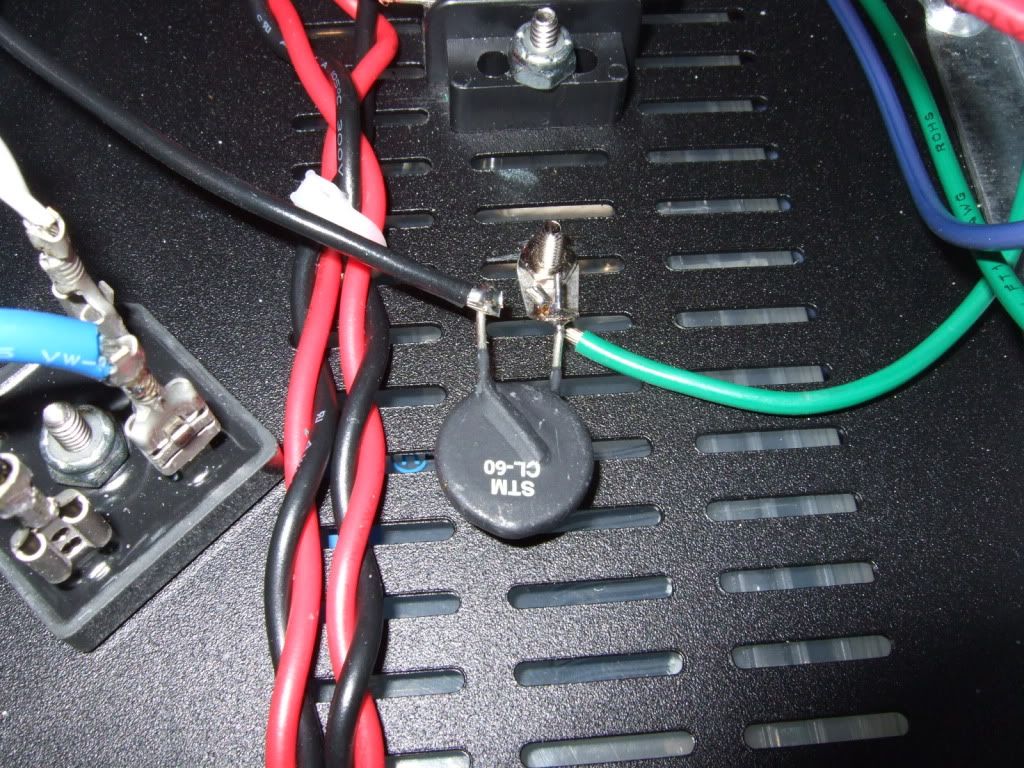
This tab actually has star washer crenellations in it, making it perfect for the application. here you see the safety earth lead (green from the IEC inlet) and the black lead connected through the thermistor to the PSU board. The thermistor does not touch the chassis except for the connection to the ground tab.
It's a bit busy over in that corner, but oh well... 🙂
So...
Um...
I'm actually to where I can power it up. I'm a bit apprehensive, as I have never built a solid state device like this before, and SS does not have the latitude that tubes give you. (which is to say, you can hammer tubes with too much current and voltage for a little while with no damage. At least long enough to measure the important things and turn it off...) My understanding is that FETs are not that forgiving...
Any advice, other than the "lightbulb in series with the hot mains lead" trick?
This is a photo of the interface that is supposed to hold the entire bottom plate to the chassis. 4 sheetmetal screws. 😕 Really? Who thought this was good idea? Anyway, It needs to be addressed...
Washers and real hardware to the rescue! This is the new interior hardware,
And this is the exterior. I have a bunch of the fender washers, so it seemed like a good place to use one. This should hold the 12lb (5.4kg) transformer and the rest of the PSU securely to the chassis.
Lastly I needed to make the chassis safety earth. So I scraped the paint (top and bottom) until bare metal was showing, and secure a bolt with star washer also on both sides. This way the star washer digs into the bare metal, making a good connection.
This tab actually has star washer crenellations in it, making it perfect for the application. here you see the safety earth lead (green from the IEC inlet) and the black lead connected through the thermistor to the PSU board. The thermistor does not touch the chassis except for the connection to the ground tab.
It's a bit busy over in that corner, but oh well... 🙂
So...
Um...
I'm actually to where I can power it up. I'm a bit apprehensive, as I have never built a solid state device like this before, and SS does not have the latitude that tubes give you. (which is to say, you can hammer tubes with too much current and voltage for a little while with no damage. At least long enough to measure the important things and turn it off...) My understanding is that FETs are not that forgiving...
Any advice, other than the "lightbulb in series with the hot mains lead" trick?
Last edited:
So...
Um...
I'm actually to where I can power it up. I'm a bit apprehensive, as I have never built a solid state device like this before, and SS does not have the latitude that tubes give you. (which is to say, you can hammer tubes with too much current and voltage for a little while with no damage. At least long enough to measure the important things and turn it off...) My understanding is that FETs are not that forgiving...
Any advice, other than the "lightbulb in series with the hot mains lead" trick?
Have a fire extinguisher handy... 🙂

Those two CL-60 in line should get really hot, so watch out for wire insulation touching them?
If you're worried about starting it up the first time (prob too late by now?), ask around to borrow a variac?
Also, seeing those painted panels, make sure all the panels have a good bare metal connection to each other for safety and decent screening. Anodizing is an electrical insulator, so watch out there as well...
One thing to do after mounting the transistors to the heatsink is check for open circuit between the hs and device (I learned this the hard way when a sil-pad got cut....)
Last edited:
.....
Any advice, other than the "lightbulb in series with the hot mains lead" trick?
certainly use lightbulb for first run
after that - if current observed at source resistors of output mosfets are gentle, and nothing is calling Geronimo! , proceed with procedure explained in CanAm's thread
well - in one of his threads ......

Threads
Zen Mod..... touche....! I think I'll start a new thread, about starting too many unnecessary new threads....
certainly use lightbulb for first run
after that - if current observed at source resistors of output mosfets are gentle, and nothing is calling Geronimo! , proceed with procedure explained in CanAm's thread
well - in one of his threads ......
Zen Mod..... touche....! I think I'll start a new thread, about starting too many unnecessary new threads....
6L6......
Just remember, in Class A amplifier DIY construction, charred resistors and torched FETs are just unkind ways of getting "aromatherapy".
Good luck on the start-up. If it's any consolation, I never was able to borrow a variac for my testing. I fired up the PSU without connections to the amp boards to confirm rail voltages. I then double-checked for good MOSFET-heatsink isolation, double-checked all amp PCB, component values and semiconductor D, G, S connections. Then I connected the PSU to one amp board and dialed in bias. Next day I did the second amp PCB. As long as a "check as you go", no problems!
P.S. In any case FETs can make great fast-blow fuses.... Best of luck!
P.S. In any case FETs can make great fast-blow fuses.... Best of luck!
Oh, great! 😀
trust me Jim , it'll sound much better plugged in 🙂
the light bulb trick cuts the rail voltage in half .
i went aluminum shopping this morning so sometime this weekend mine will be together in a proper case although it sounded pretty darn good without one .
cheers Woody
the light bulb trick cuts the rail voltage in half .
i went aluminum shopping this morning so sometime this weekend mine will be together in a proper case although it sounded pretty darn good without one .
cheers Woody
Ok, I have done the initial power up.
No Smoke! 😀
The PSU looks good, and one channel is responding to bias.
The other is acting somewhat dead, and after poking around, I see that I connected the V- to ground. I will remedy the situation and continue.
I'm exceedingly happy that my first silly mistake (I always make at least one...) Didn't blow anything up! 😎
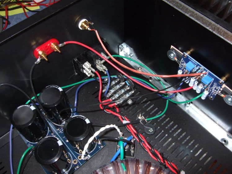
Here is more progress -
The improperly installed power lead has been fixed. As far as I can tell, everything else is fine.
Both channels are responding to bias properly. I am going to leave it alone for now and go to dinner at a friend's house, it's the year anniversary of them adopting their daughter!
When I am back from that, I will bias the amp to 90% and see how it sounds and see if it stays stable.
Zen Mod, thanks for the bias procedure, it is very clear and is working well.
6L6....Jim......
Congrats on your start-up! Sounds as though you are well on your way.
Will you end up with the Pass-recommended 0.60 volt bias, on each R11 and R12?
Curious, also--did you use the 100w lightbulb trick, or just go "stick all the way forward" approach for your first power-up?
Sent you a PM, related to your start-up.....
Ken
- Home
- Amplifiers
- Pass Labs
- How to build the F5