Compare the good channel with the bad one. Measure voltages at JFETs' Drains and Sources too (acccross 10R resistors), check orientation of protection BJTs, see how much Vgs you get at both MOSFETs with max. trimpot value, and before everything, check one more time the wiring, components' values and potential short-circuits or broken PCB lines...
Components on board exactly the same way on both boards. Checked, double-checked and triple-checked when soldering, and I measured every resistor before soldering them in place - to avoid making "stupid" mistakes per carelessness. JFETs or MOSFETs I didn't know how to measure - or that I should've done that. I'm using TechDiy component package and Peter Daniels boards.
Ok, so I should first measure voltage drop accross R1 and R2, the 10ohm resistors? With max bias setting I can get, right? Ok, will do...
How to measure "Vgs you get at both MOSFETs"?
Ok, so I should first measure voltage drop accross R1 and R2, the 10ohm resistors? With max bias setting I can get, right? Ok, will do...
How to measure "Vgs you get at both MOSFETs"?
Anybody would help me to trace a problem?
I got one channel biased to 0,52V with zero off-set. No any problem problem there. Planning to increase to 0,6V only after a couple of days in use, per Zen Mod's instructions.
Another channel. Same practice. I cannot get bias higher than 0,06V with zero off-set. What's the problem?
Maybe another case of R3 and R4 needing to be raised from 2k2 to ~3k3?
^Would you please elaborate a bit more?
To be more precise, I can certainly dial up to 0.6V, but the off-set goes to above 0.2V. Thus, this should probably be called "off-set problem" rather than "bias problem". This means off-set goes off the limits VERY early. What is strange, it'd seem as if one of the pots had much less turns prior to clicking. No, I didn't calculate the turns.
Not quite easy to measure R1 and R2 with the board screwed onto the heatsink... Anything I could measure with the power off? More safe that'd be. Checked the component values again: board and schematics do match. It should, since compared one to another back and forth - and it's only one giving me the headache now.
I was just repeating a suggestion (increase R3 and R4) for people who have problems getting full bias. And isn't low DC offset a result of getting the bias equal through both 'sides' of amp?
Yup, that's how I've understood what I should be adjusting here.
Increasing R3 and R4? Or just one - the side which seems to run out of turns? How do I know by how much to increase? It seems to go off-limits (per Mr Pass: max 50mV, preferably below 10mV off-set) in VERY low voltage. I don't know if it matters, but I have -in this problem channel- 10mV off-set already with both trimpots dialed to zero.
Most importantly... What is the actual problem for which the R3 & R4 replacement is the remedy? I do have a problematic nature in that, that I'd rather address to the problem than cover it by something else...

EDIT: Actually, what is strange, after certain voltage dialed up, the voltage accross R11 and R12 is the same, but still there is off-set in output. If I'm adjusting the bias balance - where does the off-set come from when the voltages per each side are the same? Yes, there are some gaps in my understanding here.
Increasing R3 and R4? Or just one - the side which seems to run out of turns? How do I know by how much to increase? It seems to go off-limits (per Mr Pass: max 50mV, preferably below 10mV off-set) in VERY low voltage. I don't know if it matters, but I have -in this problem channel- 10mV off-set already with both trimpots dialed to zero.
Most importantly... What is the actual problem for which the R3 & R4 replacement is the remedy? I do have a problematic nature in that, that I'd rather address to the problem than cover it by something else...
EDIT: Actually, what is strange, after certain voltage dialed up, the voltage accross R11 and R12 is the same, but still there is off-set in output. If I'm adjusting the bias balance - where does the off-set come from when the voltages per each side are the same? Yes, there are some gaps in my understanding here.
Last edited:
From the horse's mouth:
http://www.diyaudio.com/forums/pass-labs/184289-f5-bias-problem.html#post2489349
http://www.diyaudio.com/forums/pass-labs/184289-f5-bias-problem.html#post2489349
Last edited:
Help would be much appreciated
Hello smart people :]
I'm a total beginner in electronics (ok, I built Zaph SR71 speakers - but that was really easy :]) and I couldn't find anywhere whole kits for F5, so instead, that's what I got:
- 2 pcs.: 2 x 18V 300VA transformer
- stereo set of pcb for F5 from diyaudio store (just paid for it)
- stereo set of paired transistors from Hannes from Diyaudio (waiting for email with paypal data to pay)
and... that's all..
So, as You can see, I'm just at the beginning of the road with no idea what to buy more, since I can't calculate it myself from the F5 spec.
I wan't to build a dual mono construction (with best parts) with a Bride od Zen as a Pre-Amp and the best PSU's I can afford.
While looking for some more info's on the web, I recently came across that:
http://websale.compsultant.com/audio/F5AMP.xls
Looks like a kit, but can't tell if everything in there has the right values.
Knowing that, I could progress to stage: "worrying about proper soldering and getting good radiators"🙂
So if anyone smarter than me, could look at this xls, and tell me if it is right or maybe is there something, that I can improve?
Thanks in advance
Ok, thanks.
But I'm just wondering - will all the values suffice if I put a 300VA transformer for single channel?
Or do I have do change something, since it was designed for one transformer, not a dual mono build?
But I'm just wondering - will all the values suffice if I put a 300VA transformer for single channel?
Or do I have do change something, since it was designed for one transformer, not a dual mono build?
Ok, thanks.
But I'm just wondering - will all the values suffice if I put a 300VA transformer for single channel?
Or do I have do change something, since it was designed for one transformer, not a dual mono build?
You do not have to change anything...
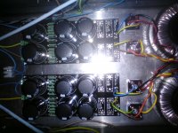
For a dual mono arrangement, I recommend that each transformer feeds a dual bridge rectifier and that each channel have it's own quite separate Main Audio Ground (MAG).
Then after testing each channel individually, you work out how to connect your two MAGs to the Chassis to make your amplifier user safe.
Then after testing each channel individually, you work out how to connect your two MAGs to the Chassis to make your amplifier user safe.
Audio,
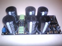
that looks like 4 diodes feeding the cap bank. 4 diodes = 1 bridge rectifier.
Are there 8 diodes in there that I can't see?
Dual rectifier for a dual mono needs 16 diodes, i.e. 4 bridge rectifiers.
that looks like 4 diodes feeding the cap bank. 4 diodes = 1 bridge rectifier.
Are there 8 diodes in there that I can't see?
Dual rectifier for a dual mono needs 16 diodes, i.e. 4 bridge rectifiers.
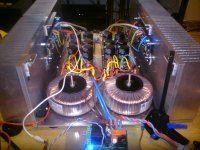
Ah, that must be the gaggle of wires going into the hidden gems behind the transformers !
Can you show the grounding schematic for the dual mono? Or is it already posted?
Can you show the grounding schematic for the dual mono? Or is it already posted?
- Home
- Amplifiers
- Pass Labs
- How to build the F5