CanAm Man
Nice motor by the way does it go around bends?
Only Joking swap that with my VR4 any time.
More pictures from me
Thinking (Oh no not again)
We got few bits in this tread.
Transformer hums twist the wires and turn it around a bit.
WHAT ABOUT DC on the LINE?
Same more small somevhere caps helps
Thermistors may get Warmer than what you like.
Artic silver 5 is capacitive
The old stuff was conductive
Tanks 6L6 for starting this up.
Next one how to mount the Mosfets.
Here is may take
Kerafoll 83/86 pads
And then ..
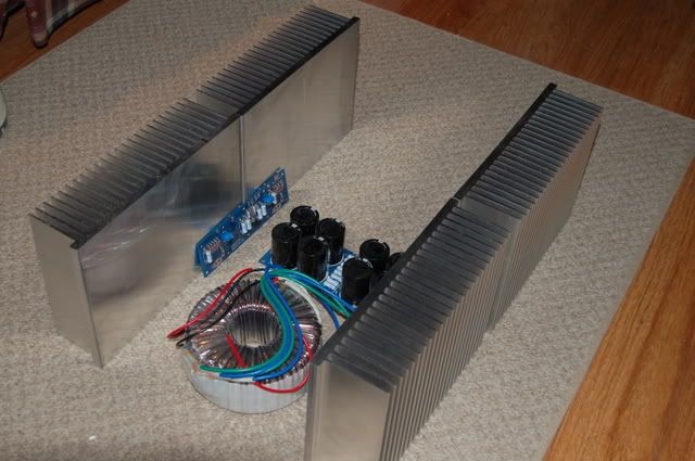
Back enclosure PSU taking shape
2 3 wrong pictures
4 Copper plate one on the right is starting to get polished /Lapped
5 Mounting on the heat sink
6 2board mounted details Toshibas on top Farchild botom
7 as abowe
8 Balanced X F5
9 Farchild TO220 FQP19N20 and beter details on difference on the cooper plates polish
2 3 wrong pictures
4 Copper plate one on the right is starting to get polished /Lapped
5 Mounting on the heat sink
6 2board mounted details Toshibas on top Farchild botom
7 as abowe
8 Balanced X F5
9 Farchild TO220 FQP19N20 and beter details on difference on the cooper plates polish
 )
)Of course they will be done
I think I got at least a good 10/20 hours to lap the lot by hand.
I had to drill the holes first and then cuntersunk.
May get to blow a few mosfets on Saturday.
Tanks for the Fugly.
I am realy in betwen chuffed and speachless state.
I think I got at least a good 10/20 hours to lap the lot by hand.
I had to drill the holes first and then cuntersunk.
May get to blow a few mosfets on Saturday.
Tanks for the Fugly.
I am realy in betwen chuffed and speachless state.
Here are potential problems I foresee with your arrangement:More pictures from me
Thinking (Oh no not again)
A. Large copper clamp is shading the rear of the heat sink and copper 'heat spreader' from convection (and radiation), and might actually have an insulating effect at the points on the heat spreader where it is the hottest (at the transistors).
B. Additional thermal interface (copper heat spreader to aluminum heat sink) might make heat sink assembly less effective overall than without heat spreader.
C. Uneven layout of transistors leads to uneven temps. (Transistor in center will be hotter than those at the edge.) (Also, why is there a lone transistor above...?)
D. Large masses of copper cause longer warm-up time. (Also, depending on which copper alloy is used, it might not have the 'strength' to act as a clamping bar -- steel would be better?)
I think it will work just fine as long as there is grease between the copper and aluminum. Is it all necessary?(the spreaders and massive everything) probably not, but is it even really necessary to make your own amp? (well WE think its necessary to make your own amp!)
Last edited:
that Bsabath thing looks as serious overkill , so - my humble ( always) opinion that there is no need to worry .....
it's an antec 5218 500 18 - 18 . i need to get to the aluminum store , used to be i could buy what i needed in a 10 min drive , these days it's an hour drive ea way and only open during my work hours 🙁
the heatsinks are 10" wide x 7" tall and i'll cut them to 8" wide . so 16 x 7 each side . way more than adequate . i need to keep it low profile . lol
the heatsinks are 10" wide x 7" tall and i'll cut them to 8" wide . so 16 x 7 each side . way more than adequate . i need to keep it low profile . lol
Andersonix
Tanks for most welcome comments.
Sorry I am not sure of what you mean for point A
B) copper conduct heat 2 time as fast as aluminium if is going to plan more heath is taken out of the mosfet and spread around a larger area.
May maybe wrong thinking make me presume that it works a bit as …
Thermal dynamics make the temperature of the glass pane of your window sit between the inside and the outside temperature so if mosfet 70 C and heat sink 50C
Cooper heath spreader 60C
C) I don’t think that is possible to avoid that when you have a number of mosfets in parallel the ones in the middle will always be hotter.
One transistor above is just for show eventually it will be same as bottom
I got a load of dust and copper Aluminium swarf to get rid off before I even think of getting the electronics out
D Yes warm up time may be to long I will need to work around that.
Variac
The back face of the copper plate is run trough quite a few passes of abrasive paper
Is flat already from the machine shop then polished on a very flat surface with paper grades starting from 60 up to 200 then 2 stages with coarse and fine polishing pads?
The final passes are done with a compound used to remove scratches from paint.
Between each pass I inspect them with blue ink for hi spots.
Rubbing the copper plate directly on the heat sink again with same fine abrasive compound does the last pass.
The anodised face of the heath sink is much harder than the copper so the copper will mate to the heat sink.
A bit like lapping the valves to the seat on the engine head.
I got same (to me) new goof made with graphite 10.5 K/mW or something like that
To get rid of the air trapped between heat sink and heath spreader.
It is conductive so is no good on the mosfet the Kerafoll 83/86 is the best (as far as I know) and does no need any goop.
Don’t get me wrong Mica is very good especially if you can make it really thin
Ever tried to stick a sheet between 2 pieces of selotape an then pull the tape apart repeat a few times and you can get same really thin stuff.
Interface should be the best I can get still….
Read the rest at your peril
I am only Joking so don’t get upset
Wako interlude>
I am waiting for Richard Branson to go to Mars (as we all know the core of that planet is solid as is been cooling down from a long time) he promised me he will try and dig out a couple of slabs of diamond he owns me
(Which is not electrically conductive) and then I can get those polished replace and sell the cooper as scrap and be rich.
Copper is running out folks so enjoy while you can.
Just in case you did not know
Al the petrol left on Mars turned in to carbon and with the time span lack of gasses and the pressure on Mars (it was actually a larger planet than Earth but all the good stuff went off on holiday) it got compressed and turned in to diamond al you have to do is dig a bit.
I was going to put same clever bit saying the American never went to Mars because there is no petrol left but I better not as I may offend somebody so I better stop the wako interlude and my writing skills are not that good any way so no big loss there.
And get back to my usual wako normal self.
At the moment there are M5 bolts holding it together (sorry for metric measure I need to get the Zeus tables out) OK M5 is just a bit less than 13/64 but eventually it will go up to M6 15/64 or maybe M8 5/16.
Again the same for the screw holding the clamps M3 1/8.
2 / 3 things about this arrangement
Bear in mind that this is only a mule an over kill for the standard F5 but it will evolve to
Triple balanced F5 (noticed how easy it is to change this with a standard board Have a look at the 8 picture and the Xed resistors)
And I got space for 12 dudes so maybe B2 A75 at a push.
Clamp bar is 5mm 3/16 it will give so yes something strong will not bend but how much pressure can you put on it before you crack the mosfet casing.
So point one
I should be able to put more pressure on the mosfet than if I was using the normal mounting screw alone (I will use Kerafol 83/86) look at the speck the more the pressure the beter it works.
Beter look at (wasit ED?) page about mounting transistors.
Sorry lost the link could some one put it back here please.
Also it will not lift and pressure is more evenly spaced.
2 no matter what mosfet I use the holes will always be the same.
3 (This is the winner for me)
Normally you clamp the mosfet with the (just to keep it simple) M3 screw how much could you pull the tread before the screw rip clean off the heat sink
You could be really good and maybe use an "Elicoil insert" once maybe 2 times.
Will that tread on the 12 mm base plate of the aluminium heath sink last for say changing mosfet 5 times?
Not if is me doing the job
So I can use M4 M5 screws to clamp the mosfet the machine head screws heads are buried in the back of the plate (picture tomorrow) the bolts are in the front
It will take much more to strip the machine screw treads or round the bolts (steel hi tensile steel) than to strip the Aluminium heath sink.
I should be able to put so much pressure on those so to actually crack the casing of the mosfet (not that I am really going to do that on purpose)
Will I be able to change mosfet say more than 5 times?
Yes I think so
And if I break the screw I just stick in a new one.
I want to change lay out no problem move the cooper plate around
The clamping holes on the heat sink are out of the way so no emmental looking heat sink for a long time.
It is a lot of bother to do it this way Yes I agree but it let me be flexible whit how many and what type of mosfet I use same holes for To220 as for 247 and Toshiba 264?
I can also swap mosfets as much as I like good for matching.
I take hours and elbow grease to lap the cooper plate
And that to me is hours of pleasure in my little loft getting blisters on my hands and cramp on my knees.
Overkill Yes it is but I am not selling this is something I made myself.
I was thinking when I started this Journey that I may need a 100 W amp I not longer convinced that I really need so much power but that’s why I started with the huge heat sinks and 1000VA transformers.
Once it works I can always cut the heat sinks and get rid of the heat speeders.
The box can be recycled as well.
So I do not worry as long as I make Papa proud...
Can’t wait to get to the front panel that is going to be a real kick.
I wonder if the thermal interface between the copper and aluminum doesn't negate the advantage of the copper heat spreader.
So do I but I have done the best I can to make it as good as possible.
The advantagge for me at this stage is that I will not strip the treads while I try different mosfets both for matching and different types for sound.
Once I am hapy the heat spreders can go
PS got those 2 plates + 2 more a bit smaller for £20 copper is at £14 Kilo so I am quids in any way.
The advantagge for me at this stage is that I will not strip the treads while I try different mosfets both for matching and different types for sound.
Once I am hapy the heat spreders can go
PS got those 2 plates + 2 more a bit smaller for £20 copper is at £14 Kilo so I am quids in any way.
Here are potential problems I foresee with your arrangement:
A. Large copper clamp is shading the rear of the heat sink and copper 'heat spreader' from convection (and radiation), and might actually have an insulating effect at the points on the heat spreader where it is the hottest (at the transistors).
B. Additional thermal interface (copper heat spreader to aluminum heat sink) might make heat sink assembly less effective overall than without heat spreader.
C. Uneven layout of transistors leads to uneven temps. (Transistor in center will be hotter than those at the edge.) (Also, why is there a lone transistor above...?)
D. Large masses of copper cause longer warm-up time. (Also, depending on which copper alloy is used, it might not have the 'strength' to act as a clamping bar -- steel would be better?)
E. Unequal expansion rates of dissimilar metal (see bi-metal bar). How will the copper be attached to the aluminum? If by screws along the edges, the unequal expansion rate may actually bulge the copper away from the aluminum.
Worth looking into
Good point but themperature differential maybe 30C so not much expansion
Got 2 plates with small gap in the midle and clerance holes around screws
Only the one in the midle of the plate has tight hole.
Still worth looking in to
Tanks
Got 2 plates with small gap in the midle and clerance holes around screws
Only the one in the midle of the plate has tight hole.
Still worth looking in to
Tanks
E. Unequal expansion rates of dissimilar metal (see bi-metal bar). How will the copper be attached to the aluminum? If by screws along the edges, the unequal expansion rate may actually bulge the copper away from the aluminum.
Worth looking into
That shouldn't be a problem based on my experience with dissimilar metals in amps. However, seeing devices "trapped" between two pieces of copper feels a bit uneasy just looking at it: http://www.diyaudio.com/forums/atta...99757968-how-build-f5-heath-spreaders-006.jpg
The outer piece will most likely get much warmer than the heatsink itself, as slab of copper does not release heat well; it behaves more as heat 'tank' and if not attached to other heat dissipating panels, may get very hot.

Last edited:
I thought it was worth mentioning. It seems counterintuitive to me to add another thermal junction anyway, and to run the risk of this junction opening up due to expansion, would be a deal breaker.
If the copper was as thick as the aluminum base, it should be fine. Inversely, if the thinner copper was a smaller area, this would be fine as well (as far as expansion goes).
If the copper was as thick as the aluminum base, it should be fine. Inversely, if the thinner copper was a smaller area, this would be fine as well (as far as expansion goes).
as copper does not release heat well, as it behaves more as heat 'tank' and if not attached to other heat dissipating panels it may get very hot.
I thought copper would release heat faster than aluminum since it conducts heat better.
I thought copper would release heat faster than aluminum since it conducts heat better.
If there is enough surface to dissipate the heat. A slab of copper is nothing like a heatsink.
I edited my previous post, as indeed, it didn't sound right.
Last edited:
- Home
- Amplifiers
- Pass Labs
- How to build the F5