You''re right a larger case makes it more easy to build into.
Found the case on Ebay, seller is along1986090
When you search his shop for "Case", you will find all types that are available. I like the look of the solid aluminium face plates.
A lot of different models available.
Already found the transistor for sale, quite expensive for 7 cent 😀
Bipolaire transistor Diotec BC 547 C NPN case TO 92 I(C) 100 mA Emitterblokkeerspanning U(CEO) 45 V
The Elco of 330uF, should that be in a specific voltage range? I would think just above 5V would do it.
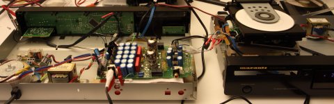
Just made the final test run with the Tjoeb only as a dac board and the CD4000 as drive. It works perfectly.
Very happy with this result!
I installed the ST to DGN jumper without a resistor. And a second one from KL to 5V with the 330 Ohm resistor.
Rev. 0.1 😀
Very happy with this result!
I installed the ST to DGN jumper without a resistor. And a second one from KL to 5V with the 330 Ohm resistor.
Rev. 0.1 😀
Attachments
Last edited:
The TekDevice board just arrived. Quite quick, so the final test can be made!
Had not checked in detail before, but power requirement is 5V. So I can directly connect it to the same connector as the Data lines on the Tjoeb board. There is a 5V line.
The data lines do almost match with the Tjoeb, so the connection is easy to do.
Tek => Tjoeb
gnd => gnd
data => data
bck => bck
lrclk => ws
Mclk => Not used
So almost plug and play. Expect to find some time to test tonight.
Just made the connections as I described above, however the only thing I get is static nose, It's starting by pressing play. So it is a signal coming from the drive.
The power led on the SPDIF EIAJ board is burning, so I have power there.
Connected a normal cinch interlink to the SPDIF in and to the digital output of a CD4000
It's only static noise, no music in it......
The setting on the board is both jumpers shorted.
GPO0=1 SDOUT=1 >> 16Bit Right Justified
All GND's are connected, both of the 5V terminal and the EIAJ output terminal.
Am I missing something?
Did you check that you actually have 5V and not more ?
Both jumpers should be 1 and thus no jumpers on the board at all according to the website: open=1
Both jumpers should be 1 and thus no jumpers on the board at all according to the website: open=1
Thx, that's it, just removed both jumpers and now it's playing🙂
So the complete project is working!
Didn't measure the voltage, but just used the 5V output on the Tjoeb board, as it is labelled 5V.
Strange that 1 is without jumpers though, always interpreted that 1 is shorted.
So the complete project is working!
Didn't measure the voltage, but just used the 5V output on the Tjoeb board, as it is labelled 5V.
Strange that 1 is without jumpers though, always interpreted that 1 is shorted.
Thanks, I'm very happy with the result. And really appreciate your help🙂
Next step is to make the muting circuit and to build the project into the new case.
The case I found should fit, however not much space above the tubes, I asked to the seller if it is possible to have the 43 cm wide case in a higher version.
I've ordered the needed electronic components and a circuit board. I also found the same connector as used on the Tjoeb board. With this I can use the same cable as inside the Tjoeb towards the muting board.
The only thing I need to think of is how to mount the DAC board in the new case, as it has only one mounting hole and the circuit board is stuffed with components till near the edge.
Regards, HJH
I'm using the DAC now for a few days in test mode, while I'm awaiting the parts and case I've ordered.
Realy like the sound I'm having🙂
There a no pops when powering up the DAC, the only pop I have is when I shut it down, so the other way around.... Not severe but would be nice if it can be avoided.
I was thinking about some sort of delay in shutting down the Tube relay, is this possible?
And secondly would you have some advice on the internal wiring to use toward the Cinch connectors?
Thx and regards, HJH
Just found today a PSU delay circuit on Ebay
Tube amplifier PSU delay circuit assembled ! | eBay
Would this working principle be something to prevent the pop at shut off?
I was thinking about a delay for the main power relay, as then the output relay is shut off first and after a few seconds the Main relay. This in the opposite as switching on with the delay scheme.
All parts for the delay scheme have arrived, so I started to build and lay out the circuit board. Ordered connectors today for the internal wiring, so things are progressing nicely.
Thx, HJH
Just was surfing again for an option to delay the power off. Don't know if the Tube delay I found would do the job. However found a different scheme on YouTube:
Power Off Time Delay Relay Circuit - YouTube
Would this do the job? Then I could have a circuit for every relay in place.
Thx, HJH
Power Off Time Delay Relay Circuit - YouTube
Would this do the job? Then I could have a circuit for every relay in place.
Thx, HJH
- Status
- Not open for further replies.
- Home
- Source & Line
- Digital Source
- How to build a Digital input on a Njoe Tjoeb 400 (Marantz CD 4000) cd player