Hello j wilhelm
greetings any update on the acs overcurrent project
warm regards
Andrew
Hi Andrew.
I've got some sensors on prototype boards, but haven't had any time to experiment with them yet. They look pretty easy to work with. Simple 0 - 5V signal conversion.
After a considerable amount of time, I finally got my honey badger build together. Apart from one DC protection board it is all working now.
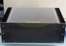
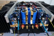
The case was built from scratch, with two 300x165mm heatsinks and a lot of metal. I'm pretty pleased with it overall, it looks reasonably well finished.
In short both the honeybadger and the protection board are working really, really well. The overload or DC protection was kicking in when in my AV cabinet, but that was because it was powering up in the wrong sequence, power stage coming on after the pre amp, causing a temporary overload.
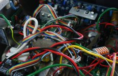
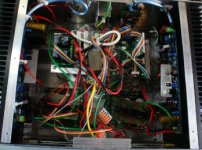
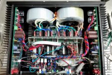
It's a bit messy inside at the moment, because it is still unfinished really. However, a couple of photos are attached, and for those that are interested, a link to my blog with a more detailed overview of how I built it.
I feel I've learnt an awful lot building both the amp and the protection board. Now, I've got some plans for my turntable and a few Arduino projects..
Building DIYAudio's honey badger amplifier
The case was built from scratch, with two 300x165mm heatsinks and a lot of metal. I'm pretty pleased with it overall, it looks reasonably well finished.
In short both the honeybadger and the protection board are working really, really well. The overload or DC protection was kicking in when in my AV cabinet, but that was because it was powering up in the wrong sequence, power stage coming on after the pre amp, causing a temporary overload.
It's a bit messy inside at the moment, because it is still unfinished really. However, a couple of photos are attached, and for those that are interested, a link to my blog with a more detailed overview of how I built it.
I feel I've learnt an awful lot building both the amp and the protection board. Now, I've got some plans for my turntable and a few Arduino projects..
Building DIYAudio's honey badger amplifier
Attachments
Nice job! Home brew chassis are as much work as the rest of the amplifier.
What's the DC detection doing on the faulty channel? I don't remember which version I sent you. We've done some revisions on the resistor values to lower current consumption/heat. We've also discovered a glitch causing false triggering on the SMT versions due to power supply ripple that's easily corrected.
Your startup issues sound interesting. This sounds like the glitch we discovered in the SMT version. I've done the same alterations in the new through hole versions. This may be what you've got happening.
Nice job! Home brew chassis are as much work as the rest of the amplifier.
What's the DC detection doing on the faulty channel? I don't remember which version I sent you. We've done some revisions on the resistor values to lower current consumption/heat. We've also discovered a glitch causing false triggering on the SMT versions due to power supply ripple that's easily corrected.
Your startup issues sound interesting. This sounds like the glitch we discovered in the SMT version. I've done the same alterations in the new through hole versions. This may be what you've got happening.
Hi Jeff,
I suspect the false trigger is occurring when my Arcam AV unit turns on and there is a temporary spike on its pre-outs at that point. To be honest I had gotten around that by adjusting start order, and making the power amp dependent on the AV receiver being on (using the 12V line). Nether the less, if there is an easy adjustment I could make, I'd like to make it. I have the SMT DC board BTW with built in holes for the binding posts, with the changes already made to lower current flow.
As for the faulty DC unit, it does not properly switch the channel on, leaving the channel off, it was initially intermittent, but got to the point now where it does not work. To be honest, I've not had a lot of time to look at it recently, but what I do know is:
The DC alarm is not being triggered,
The DC rail voltages are being fed to the right places
I suspect it was my fault, I soldered in the optos and MOSFETs without taking proper (any) static precautions. Maybe I'll try and have a look at soon, but I'm enjoying the sound so much, it's difficult to take it apart.
Dave.
The Badger input is AC coupled if I recall correctly, so the Arcam should't be triggering the detection circuit.
The optos are very rugged. It's unlikely you damaged them. More likely a bad solder joint somewhere. You will need to take a couple voltage readings on the inputs and outputs of the optos to see what is happening. The optos are dual packages and the inputs of each package are in series. you should start there and see if you are getting a couple volts across the inputs telling the optos to turn on.
If you add two 1M resistors and one 1uF capacitor in 1206 packages to each DC detection board they will be much less likely to false trigger from ripple in the supply rails. Stack the 1uF capacitor with R2 and stack the 1M resistors with D3 and D4.
I added this same DC detection circuit to my Modular NS-OPS plate amp board and took the positive rail feed for the detection circuit from between a couple output devices and had terrible false triggering. We found there was a DC voltage building up on the bases of Q1 and Q2 with a dirty supply so we added 1M resistors to bleed some of this off and added the cap in parallel with R2 to take a bit of the ripple off.
My plate amp now triggers with 35VRMS square waves on the output but no issues at all with sine waves or music. I think having it trigger with high power sine waves is probably a good thing, as the sine wave would likely damage a speaker so I left it like that.
Last edited:
I've got to say that one thing I had underestimated is how much space all the components in the chassis would take up. My original plan was for a integrated amp, but I have no idea where I'd fit the pre-sections, there is so little space left in the box now, and that is with the entire control circuitry raised above the transformer.
My pre-amp will probably end up being external at this point to be honest.
My pre-amp will probably end up being external at this point to be honest.
The Badger input is AC coupled if I recall correctly, so the Arcam should't be triggering the detection circuit.
The optos are very rugged. It's unlikely you damaged them. More likely a bad solder joint somewhere. You will need to take a couple voltage readings on the inputs and outputs of the optos to see what is happening. The optos are dual packages and the inputs of each package are in series. you should start there and see if you are getting a couple volts across the inputs telling the optos to turn on.
If you add two 1M resistors and one 1uF capacitor in 1206 packages to each DC detection board they will be much less likely to false trigger from ripple in the supply rails. Stack the 1uF capacitor with R2 and stack the 1M resistors with D3 and D4.
I added this same DC detection circuit to my Modular NS-OPS plate amp board and took the positive rail feed for the detection circuit from between a couple output devices and had terrible false triggering. We found there was a DC voltage building up on the bases of Q1 and Q2 with a dirty supply so we added 1M resistors to bleed some of this off and added the cap in parallel with R2 to take a bit of the ripple off.
My plate amp now triggers with 35VRMS square waves on the output but no issues at all with sine waves or music. I think having it trigger with high power sine waves is probably a good thing, as the sine wave would likely damage a speaker so I left it like that.
Many thanks, I'll take the readings and give those changes a try and let you know how it goes.
I've got to say that one thing I had underestimated is how much space all the components in the chassis would take up. My original plan was for a integrated amp, but I have no idea where I'd fit the pre-sections, there is so little space left in the box now, and that is with the entire control circuitry raised above the transformer.
My pre-amp will probably end up being external at this point to be honest.
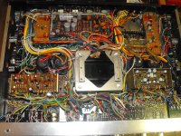
Yes they do fill up fast. I've found with these high power amps you really need to plan the whole amplifier layout before you even start to think about building or you run out of room fast.
Just like a pcb layout, the placement is critical to success. It helps to look at other amp designs and base your work off them. Pick the neat ones. The high power receivers can pack it in there. I have a pioneer qx-9900 that is packed to the limits. wires everywhere.
Attachments
Rick - totally agree, the same topology can be a great success of a complete fail, depending on the way it's built.
Here are a few good examples of rather packed, but well-structured builds:
1) Gryphon Antileon EVO internals - note the "rails", connecting the output terminals to the main ground and the amp boards' outputs 😱
2) Vertical CFA + NS-OPS combo boards amplifier reference build on the test bench, done by Jeff (front panel is at the top). High output currents capability, very low noise, good heat dissipation. Although, this is not the latest version, it's still very well-arranged.
Cheers,
Valery
Attachments
Did you try these tube amp control boards yet? Finally have some time to start tinkering with my controls again.I've got a complete tube amp control board with dual high voltage detectors on board. It's on a 4" x 6" board. I still want to print the board and test fit parts to make sure everything goes before ordering boards.
Documentations
Hi Jeff / Valery
I have recently acquired the following from a member (passive420):
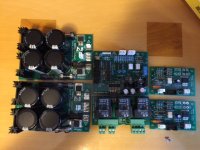
1. Compact Supply II (3/12/16) x2
2. Amp Control 4.3
3. Power Relays 2.2
4. Speaker Protect 3.2 EvanC Version x 2
I intent to use them for the VFET kit. I tried going through this thread to look for documentations (BOM, build guide, wiring diagrams etc.) but am confused with the different versions of the different modules.
I would be a huge help if you may post here of send me (see PM for my email) the relevant documentation for putting your system into good use.
Thanks!!!
Tim
Hi Jeff / Valery
I have recently acquired the following from a member (passive420):
1. Compact Supply II (3/12/16) x2
2. Amp Control 4.3
3. Power Relays 2.2
4. Speaker Protect 3.2 EvanC Version x 2
I intent to use them for the VFET kit. I tried going through this thread to look for documentations (BOM, build guide, wiring diagrams etc.) but am confused with the different versions of the different modules.
I would be a huge help if you may post here of send me (see PM for my email) the relevant documentation for putting your system into good use.
Thanks!!!
Tim
Attachments
Hi Tim,
Nice set! Jeff has designed all these latest boards and got all the respective docs - he will contact you 😉
Cheers,
Valery
Nice set! Jeff has designed all these latest boards and got all the respective docs - he will contact you 😉
Cheers,
Valery
Jeff, if you have extra boards available I would be interested in buying a few. Also do you know where the Gerbers are for this project?
I have a similar board and project done however it is not as complete. I am using 2 5v relays - 1 is zero non crossing and 1 is a SSR and I am using the arduino to do the soft start, thermal shut down as well as fan controlling. I have a number of 12v relays here as well as the off the shelf 5v relay boards and I would like to add a 12v trigger, DC sensing protection, etc. Can I use the 5v relay boards connected to the arduino with a voltage rail sensing the DC? What do I need to do to add some kind of DC sensing where the arduino would then activate the relays at 5v based on the polling? IE. 12v DC trigger would turn on the amps, DC detection in line out would shut them down, etc.
I have a similar board and project done however it is not as complete. I am using 2 5v relays - 1 is zero non crossing and 1 is a SSR and I am using the arduino to do the soft start, thermal shut down as well as fan controlling. I have a number of 12v relays here as well as the off the shelf 5v relay boards and I would like to add a 12v trigger, DC sensing protection, etc. Can I use the 5v relay boards connected to the arduino with a voltage rail sensing the DC? What do I need to do to add some kind of DC sensing where the arduino would then activate the relays at 5v based on the polling? IE. 12v DC trigger would turn on the amps, DC detection in line out would shut them down, etc.
I've got lots of boards available. I need some info on your build configuration to be able to recommend boards for it. It's easier if you contact us through our website for info. Virtual Zero Audio - power amplifier products
After a somewhat long break, I've finally got around to starting to apply the newer compact power supply PCB's that Jeff sent me a couple of months back. I'm working through slowly. Now, I've got both boards working with the mosfets hardwired to ON, and I'm just starting on getting the PSU digital control working.
BTW: just realised today why I've been having on-off problems with my FTDI lead, I mistakenly bought a 3v3 one! I'm assuming that is just not going to work / probably now broken.
Will feedback again once I have the right FTDI cable.
BTW: just realised today why I've been having on-off problems with my FTDI lead, I mistakenly bought a 3v3 one! I'm assuming that is just not going to work / probably now broken.
Will feedback again once I have the right FTDI cable.
After a somewhat long break, I've finally got around to starting to apply the newer compact power supply PCB's that Jeff sent me a couple of months back. I'm working through slowly. Now, I've got both boards working with the mosfets hardwired to ON, and I'm just starting on getting the PSU digital control working.
BTW: just realised today why I've been having on-off problems with my FTDI lead, I mistakenly bought a 3v3 one! I'm assuming that is just not going to work / probably now broken.
Will feedback again once I have the right FTDI cable.
Hi, good to know you're progressing

You're right - Atmega328 chip, running from +5V supply, requires 5V FTDI. 3v3 one may not break at 5V, but it's not expected to work properly because of the different signal levels anyway.
The 3V3 version of the FTDI adapter is fine. They are 5V tolerant and the atmega328 will communicate fine at 3V3. The intermittant com issues are usually Windows/driver problems. FTDI has added killer code to their drivers to brick clone versions of their ICs but it can't tell the real ones from the fake. I've stopped using their products completely.
- Home
- Amplifiers
- Solid State
- How to build a 21st century protection board