[QUOTE="ginetto61]
Have you performed tests like the Stereophile tests on some speakers ?
that could be the decisive test.
[/QUOTE]
Hi gino,
Accelerometer data is not "radiated sound" data, i have already covered this topic in earlier posts.
Bracing pulls visible (measured) acceleration (and velocity) of the walls down but nevertheless increases efficiency of unwanted sound radiation and audibility.
In fact - only selective - accelerometer data only seems rather pointless in itself, as the viewer cannot know how to translate the pictures to "unwanted sound radiated".
And frankly speaking: I don't believe testers at "stereophile" do know how to achieve this either. Thus "just not publishing data, which virtually no one can interpret correctly" seems the better way to go IMO.
I use e.g. modern hight tech imaging methods like these 😉 :
Ernst Chladni - Wikipedia, the free encyclopedia
http://www.dipol-audio.de/projekt-s..._Decke/10_220Hz_Decke_NachCa10Sekgestoppt.jpg
from:
Schwingungen an Lautsprechergehusen
The picture shows the nodeline of the lowest mode (220Hz) in two identical subwoofer enclosures i made some years ago. That nodeline in fact forms a kind of ring, which is located closely behind the hidden baffle carrying the driver. That modal shape is very similar to those found in bells btw.
The woofer's baffle is at the hidden side, as both subwoofers are standing with drivers "face to face" on the ground. Now the question:
If i want to push that 220Hz mode even further up (considerably) in frequency, which kind of bracing would be most effective ?
Kind Regards
Last edited:
Now the question:
If i want to push that 220Hz mode even further up in frequency, which kind of bracing would be most effective ?
Kind Regards
Divide the panel in 2 (or more) parts that resonate by adding a panel perpendicular to it?
You mean like an "inner ring" shaped brace at about half the depth of the enclosure ?
Like the yellow one ?
http://www.lautsprechershop.de/hifi/images/box_stuetz.gif
Like the yellow one ?
http://www.lautsprechershop.de/hifi/images/box_stuetz.gif
Last edited:
You mean like an "inner ring" shaped brace at about half the depth of the enclosure ?
I think a "cross" inside the cabinet with wide panels (about 1/2 to 2/3 the width of the panel to be braced) should be better.
Like the blue one in the picture.
OK, that is surely an option many would opt for, and seems reasonable at first glance.
In fact this subwoofer cabinet does not need further bracing, but if i was to push the mode up i would first make just a thicker baffle holding the driver, e.g. with double thickness (19mm >> 38mm).
The nodeline is very close to the small baffle at the front, which indicates, that there is very slow propagation of bending waves on the baffle, while propagation is faster at the rear of the cabinet.
This is because the driver's basket and motor - which has considerably higher mass than the wood that has been cutout from the baffle - leads to "low stiffness and high mass per area" in that front baffle zone of the cabinet, where the driver is bolted to.
Here is the zone, where an increased stiffness will yield the largest effect by using the least amount of material.
The baffle is rather small - due to the in depth stretched shape of the cabinet - and doubling it may yield stiffness x8 in that zone, which has high strain currently.
This would be my first step. Again i would not go for conventional "bracing", but make this special "panel" more thick.
But i don't expect the resonance will move up over say 300Hz or so by doing so, and i would have to pay in terms of "higher audibility" of the resonance, so i leave it as it is, because it is "nearly perfect".
Rather i would add some damping, to reduce the mode in Q, although it is "fairly out of the used band already", since the subwoofer is designed to be low-passed at 80Hz.
Kind Regards
Hi gino,
Accelerometer data is not "radiated sound" data, i have already covered this topic in earlier posts... Kind Regards
Hi and thanks again. I understand now that the all issue is a little too complex for me to understand
But just two other very short questions:
1) you say the accelerometer data do no give a measure of the radiated sound. But if a panel does not move there is no radiated sound isn't it ?
A still panel does not radiate anything.
And the accelerometer measures the displacement of the panel with frequency
2) speaking of the front baffle i see you prefer to double the thickness of the very important front panel instead of bracing it. This is extremely interesting to me because the front baffle construction is indeed one of my biggest obsessions. In the end is the panel where the drivers are mounted on. It it moves also the sources of sounds will move.
To end i attach hereunder a picture of a braced front baffle in a normal speaker ... epos es11. It is plastic 🙂eek🙂 and braced 😱
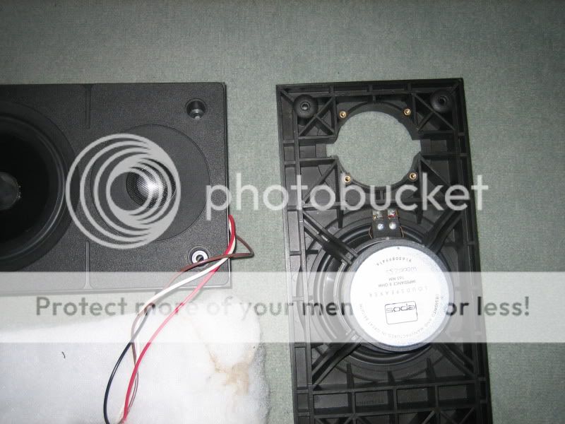
and seems to work by the way.
But i would like to understand why you prefer to double the tickness.
I guess that in this way you add also not only stiffness but also mass and so damping that is good.
2 nice things with one move ...
Thanks a lot again, gino 😀
Last edited:
The Epos 11 needs some crossover work, IMO. It's a silly first order filter.
I always think that if you can't explain something SIMPLY, then you don't understand it. 🙂
I am loving this discussion, even if it's getting a bit nebulous referring to 18C German scientists playing with sand-patterns. 😀
Here's the facts of it. Most cabinet resonances are excited by the "Seismic" mass of the cone. In fact we could lose cabinets altogether if we played with Steen Duelund's ideas.
My brother-in-law has some 15" bass cones in in-wall brick-built cabinets which sound rather good. He's had to strengthen the house foundations to get away with this mass, but whatever.
What is strange about most modern ideas, is that acoustic efficiency is around 1% for most of the audio range. A car that ran like that would be dismissed instantly.
In one of the most staggering Volte-Faces of modern audio, my good friend Lynn Olson, has moved away from little inefficient 5" drivers in a heavy cabinet to 100 dB 15" JBL drivers with horn tweeters.
http://www.diyaudio.com/forums/multi-way/100392-beyond-ariel.html
So there's two schools of thought on this. Heavy low-efficiency, or light high-efficiency. So what I'm thinking, is take any old good cabinet, and throw in a light-coned high-efficiency driver, and you are golden.
Which is why I think my Visaton W200S driver works so well. A Qms of 3.6 is exceptional. 😎
I always think that if you can't explain something SIMPLY, then you don't understand it. 🙂
I am loving this discussion, even if it's getting a bit nebulous referring to 18C German scientists playing with sand-patterns. 😀
Here's the facts of it. Most cabinet resonances are excited by the "Seismic" mass of the cone. In fact we could lose cabinets altogether if we played with Steen Duelund's ideas.
An externally hosted image should be here but it was not working when we last tested it.
My brother-in-law has some 15" bass cones in in-wall brick-built cabinets which sound rather good. He's had to strengthen the house foundations to get away with this mass, but whatever.
What is strange about most modern ideas, is that acoustic efficiency is around 1% for most of the audio range. A car that ran like that would be dismissed instantly.
In one of the most staggering Volte-Faces of modern audio, my good friend Lynn Olson, has moved away from little inefficient 5" drivers in a heavy cabinet to 100 dB 15" JBL drivers with horn tweeters.
http://www.diyaudio.com/forums/multi-way/100392-beyond-ariel.html
So there's two schools of thought on this. Heavy low-efficiency, or light high-efficiency. So what I'm thinking, is take any old good cabinet, and throw in a light-coned high-efficiency driver, and you are golden.
Which is why I think my Visaton W200S driver works so well. A Qms of 3.6 is exceptional. 😎
Last edited:
ginetto61 said:1) you say the accelerometer data do no give a measure of the radiated sound. But if a panel does not move there is no radiated sound isn't it ?
A still panel does not radiate anything.
And the accelerometer measures the displacement of the panel with frequency
Hi gino,
all you say is true IMO.
But e.g. bracing changes "phase speed of bending waves" on the panel.
Higher phase speed makes radiation of sound more efficient.
A modally vibrating cabinet e.g. made of thin soft rubber sheets may have high amplitude of the walls, but propagation of bending waves is so slow, that sound radiation is very low (inefficient).
The stereophile guys would - in this case - measure "high wall acceleration" even at this virtual rubber cabinet. Nevertheless radiation would be low ...
Placing an acceleromenter somewere to a cabinet does not allow precise conclusions about sound radiation in itself, because a more complete set of parameters would be needed.
- amplitudes
- shape of modes (grid of accelerometers or scanning interferometer needed)
- coincidence frequency of the cabinet (at which frequency will bending waves propagate as fast as sound in air? This is dependent from cabinet material and thickness e.g.)
Phase speed of bending waves rises with frequency, thus efficiency of radiation rises with frequency, also audibility rises with frequency.
Furthermore with "bracing only" the Qs of the modes rise and the freqencies rise too.
It should have bacome clear by now, that "bracing only" is like playing with fire due to unwanted sound radiation and audibility.
Please see
http://www.diyaudio.com/forums/multi-way/235908-how-brace-speaker-cabinet-6.html#post4178163
.. and say the following 2 or 3 of my posts after that.
Last edited:
ginetto61 said:speaking of the front baffle i see you prefer to double the thickness of the very important front panel instead of bracing it. This is extremely interesting to me because the front baffle construction is indeed one of my biggest obsessions. In the end is the panel where the drivers are mounted on.
In that special case of my little subwoofer, i could have made the front baffle stiffer in order to push the lowest mode at 220Hz up.
Doing this by "bracing", i would need some kind dwarfs to do the filigrane woodwork, so "doubling" is the economic way IMO.
The effect is 8 times the stiffness and only twice the mass of the baffle ...
If we think of relations, we added just stiffness to the baffle, as the driver is still more massive than the baffle (doubled or not ...).
http://i56.photobucket.com/albums/g194/stuartfrazer/Epos 11/IMG_1671.jpg
Hi gino,
that baffle structure you are showing may be fairly stiff, but depending on material might be underdamped. Maybe if made from PP damping is even very acceptable (but doesn't look like PP).
If the cavities were filled with some dampening stuff (also contributing some mass ...), that baffle could be a "killer" even for widerange application ... (bass to midrange).
But also contributes to pollution if not disposed properly after "product lifetime".
Kind Regards
Hi gino,
that baffle structure you are showing may be fairly stiff, but depending on material might be underdamped. Maybe if made from PP damping is even very acceptable (but doesn't look like PP).
If the cavities were filled with some dampening stuff (also contributing some mass ...), that baffle could be a "killer" even for widerange application ... (bass to midrange).
But also contributes to pollution if not disposed properly after "product lifetime".
Kind Regards
Last edited:
What is happening in terms of bending waves to prevent the panel vibrating at the nodes?The nodeline is very close to the small baffle at the front, which indicates, that there is very slow propagation of bending waves on the baffle, while propagation is faster at the rear of the cabinet.
There is no movement at the nodes ... so there is little you can influence there:
Neither damping nor bracing may be applied sucessfully directly at a nodeline. Or am i missing something ?
Neither damping nor bracing may be applied sucessfully directly at a nodeline. Or am i missing something ?
An accelerometer measures the vibration at a point on the panel. This point might be sitting on a node and not vibrating (e.g. aligned with one of the B&W internal matrix stiffening panels) or sitting on an anti-node and vibrating a lot (e.g. between the internal stiffening panels). Where did Stereophile place their accelerometer for the first few mode shapes?1) you say the accelerometer data do no give a measure of the radiated sound. But if a panel does not move there is no radiated sound isn't it ?
A still panel does not radiate anything.
And the accelerometer measures the displacement of the panel with frequency
If one wishes to investigate sound from a vibrating cabinet one needs to measure at a lot of points over the whole enclosure. You need not only the magnitude but the phase as well in order to know which parts of the panel are going in and which are going out with respect to each other. The spacing between the points needs to be close enough to resolve the mode shapes of the highest frequency of interest.
Hi
Been following this thread with a lot of interest. I have a friend in the audio business
who has developed a particular construction method for loudspeakers that seems to work for me. However in the light of what has been discussed so far I wonder what you think of his reasoning. I know this is a DIY site and this method is perhaps not easily suitable for home construction but it might be.
First the outer box of the speaker is made of welded mild steel of 2mm thickness ( I
think). This is rustproofed and then lined with bitumen pads again of approx 2/3mm.
Then a 15mm layer of a particular grade of plaster mixed with chopped glass fibre
is poured over all internal surfaces. As the plaster sets it expands slightly puttting the
outer shell under tension. The walls are lined with some kind of acoustic damping material.
So what you have is a high mass high stiffness CLD box which seems to meet the requirements mentioned in this thread. Sadly I have no measurements but hope to
put that right when I can get an accelerometer working properly.
andy19191 said:If one wishes to investigate sound from a vibrating cabinet one needs to measure at a lot of points over the whole enclosure. You need not only the magnitude but the phase as well in order to know which parts of the panel are going in and which are going out with respect to each other. The spacing between the points needs to be close enough to resolve the mode shapes of the highest frequency of interest.
... well put
 .
.
Last edited:
If a single bending wave is travelling across a panel it will throw off the sand everywhere. If a random set of bending waves is travelling across a panel it will throw off the sand everywhere. So what is happening to give us a pattern of nodes and anti-nodes in terms of bending waves? What changes in this node and anti-node pattern above and below your critical bending speed?There is no movement at the nodes ... so there is little you can influence there:
Neither damping nor bracing may be applied sucessfully directly at a nodeline. Or am i missing something ?
andy19191 said:What is happening in terms of bending waves to prevent the panel vibrating at the nodes?
Of course a nodeline separates zones vibrating in opposite phase ...
i think this is, what you're referring to ?
The (say) positive zone around the driver cutout on the baffle is rather small in my example enclosure. The (say) negative zone (spread over nearly the whole rest of the cabinet) is rather large.
So "bending wavelength" is considerably smaller at the baffle zone:
High mass and low stiffness there yields slow propagation of bending waves.
andy19191 said:So what is happening to give us a pattern of nodes and anti-nodes in terms of bending waves?
In my example subwoofer cabinet, that 220Hz mode e.g. is a standing wave pattern.
- the baffle moves in an out at high amplitude.
(max amplitude is expected at the drivers magnet as being a "mass center")
- the rear part of the cabinet (throwing the powder off) makes also a (more distributed) "belly" moving in and out, thereby moving in antiphase to the "baffle&driver belly".
- and the nodeline separating the vibrating zones is somewhere behind the baffle.
(visible by the powder settling ...)
Of course the pattern looks similar for the side walls too, this is why i concluded, the nodeline being ring shaped basically. It is not visible in the single picture i posted, as i unfortunately also need gravity for the powder to settle ... 😉
Last edited:
andy19191 said:What changes in this node and anti-node pattern above and below your critical bending speed?
In a simplified one dimensional structure - say a rod clamped at both ends - multiples of half wavelenghts have to fit on the rod.
Then you get bending wave modes at 1 lambda/2, 2 lambda/2, etc.
Same as in (both side closed) organ pipes filled with air.
Difference is just bending wave's phase speed increases with frequency (are dispersive). But you cannot "see" that when observing a single mode.
In fact with dispersion "the next higher mode" is always higher in frequency than it would be in a non dispersive medium.
Dispersion hampers the increase of "modal density" with frequency a bit ...
___
The "coincidence frequency" - were bending wave's phase speed is same as sound in air - is not a property of the vibrating panel itelf and has no influence on the shape of modes.
Coincidene frequency is just related to the surrounding medium (mostly air is of interest). Around and above the coincidence frequency, a bending wave radiator ( a panel or a cabinet structure) radiates sound very effectively.
Far below the coincidence frequency it does not ...
This is one reason to keep the coincidence frequency of a cabinet's walls high enough (bending wave propagation slow enough ...)
In this respect "fast" materials (lightweight and stiff) are critical, because those may only be used at lower frequencies to make a "low radiation" cabinet from.
But what makes a panel "fast" is also thickness:
Double thickness gives 8 times stiffness but only 2 times mass per area.
The ratio "stiffness" by "mass per area" is part of the "dispersion relation" to calculate the phase speed of bending waves, also is the frequency.
http://de.wikipedia.org/wiki/Biegewelle#Gruppengeschwindigkeit
Last edited:
What is the physical explanation for a single travelling wave in a panel substantially changing the amount of sound radiated to the far field above and below the coincidence frequency? Now consider the standing waves in your cabinet shown to be present by your sand. Does this explanation hold for standing waves?Coincidene frequency is just related to the surrounding medium (mostly air is of interest). Around and above the coincidence frequency, a bending wave radiator ( a panel or a cabinet structure) radiates sound very effectively.
PS The answer is yes from superposition (I think).
Last edited:
- Status
- Not open for further replies.
- Home
- Loudspeakers
- Multi-Way
- how to brace a speaker cabinet?