hi all
yesterday I asked people for helping me to learn how to bias a srpp
today I found sth useful
forgive me cause that this type of question maybe very common and simple
SRPP Amplifier Theory / Pictures | TTRadio
the following website showed sth very useful for people who wants to know about srpp and how to bias and calculation and....
everythings that the author wrote on his website is ok
no problem
my question is his bias point
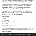
in the last page he wrote that:R=RAK=RK=3.3K ohm
we know that in srpp for two identical tubes,the current for both is equal when we input no signal,and the voltage for each one will be half of the B+
I wanna know that for finding the optimim point of bias,he used 150v for the exact point of bias? or the same 300v?
yesterday I asked people for helping me to learn how to bias a srpp
today I found sth useful
forgive me cause that this type of question maybe very common and simple
SRPP Amplifier Theory / Pictures | TTRadio
the following website showed sth very useful for people who wants to know about srpp and how to bias and calculation and....
everythings that the author wrote on his website is ok
no problem
my question is his bias point
in the last page he wrote that:R=RAK=RK=3.3K ohm
we know that in srpp for two identical tubes,the current for both is equal when we input no signal,and the voltage for each one will be half of the B+
I wanna know that for finding the optimim point of bias,he used 150v for the exact point of bias? or the same 300v?
Attachments
Last edited:
I suspect that analysis is flawed. He replaces each valve in turn by a short circuit. He should have replaced each by their anode impedance, in my opinion. Hence it is likely that all his formulas are wrong. See the Valve Wizard site for a better analysis.
typical newbie reaction is to look at tubes as if exact values to the decimal point is possible..
a triode common cathode will seek its plate current with a given cathode resistor, tube variations will not make exact results if that is what he is asking...
nor 1/2 b+ with 300 vdc will not give you exactly 150 vdc, it is possible, but expect a slight variation of a few volts...
a triode common cathode will seek its plate current with a given cathode resistor, tube variations will not make exact results if that is what he is asking...
nor 1/2 b+ with 300 vdc will not give you exactly 150 vdc, it is possible, but expect a slight variation of a few volts...
I suspect that analysis is flawed. He replaces each valve in turn by a short circuit. He should have replaced each by their anode impedance, in my opinion. Hence it is likely that all his formulas are wrong. See the Valve Wizard site for a better analysis.
I checked valve wizard and found nothing useful related to srpp
you mean that at the final of calculation,he achieve to formula of gain and R Load,both of them are wrong?
typical newbie reaction is to look at tubes as if exact values to the decimal point is possible..
a triode common cathode will seek its plate current with a given cathode resistor, tube variations will not make exact results if that is what he is asking...
nor 1/2 b+ with 300 vdc will not give you exactly 150 vdc, it is possible, but expect a slight variation of a few volts...
for the both identical triodes can this happens?
I checked valve wizard and found nothing useful related to srpp
you mean that at the final of calculation,he achieve to formula of gain and R Load,both of them are wrong?
Did you find this at all?
https://www.google.com/url?sa=t&source=web&rct=j&url=http://www.valvewizard.co.uk/SRPP_Blencowe.pdf&ved=2ahUKEwiYo5OpvZfmAhVUqZ4KHf0cDo0QFjAAegQIBhAC&usg=AOvVaw0-B2METkjf7gv223jopjPu&cshid=1575307463940
for the both identical triodes can this happens?
With "identical" and ideal triodes the plate of the bottom triode should be at exactly 1/2 of the supply voltage, assuming identical cathode resistor values. In real life it would not be unusual to see this vary by 5-10% or so due to manufacturing variations causing no two triodes to be perfectly identical. Matched triodes can make things closer to ideal, although this is rarely required, as it won't make much of a practical difference in use.
See SRPP_Blencowe.pdfMamaReza said:I checked valve wizard and found nothing useful related to srpp
I don't know. I would not trust them, given that they were derived incorrectly. Use The Valve Wizard formulas.you mean that at the final of calculation,he achieve to formula of gain and R Load,both of them are wrong?
- Home
- Amplifiers
- Tubes / Valves
- how to bias a srpp circuit