Hello guys,
I'm working on a new amp, and I have some trouble to bias a pentode ... I don't know how to do it ... I'm ok with triode ... but pentode ... I fail.
My needs are more than 200 Vpp output for an input around 2/3 Vpp. I will use some feedback ... so I need more than a 6SL7, that's why I use pentode. My HT will be around 430~450 V for the pentode.
I have selected the E80F pentode. Data sheets are here : http://frank.y ueksel.org/sheets/030/e/E80F.pdf or here : http://frank.yueksel.org/sheets/009/e/E80F.pdf
Did you know some good sounding bias point for this E80F ?
And well how to deal with pentode bias ... ? First : Ug2. If I understand the use, more Ug2 more grid recoil is available for the same bias point ?
Second : How to define Ra load correctly ? If I load it low (like Ra = 40k Ohms) the loadlines is really vertical, and I suppose lots of distortion because there is lots of more voltage at the left side than the right side of bias point. If I load it high (like Ra = 150k Ohms) the loadlines goes in the left where the curves are really rounded ... And the voltage drop into Ra could be huge ...
So I don't know what to do and how to correctly bias thoses E80F to get 250 Vpp at the outpout ...
I have try it without succes 🙁 Could you help me please ?
Thank you in advance !
Attachments
Last edited:
My last try for today :
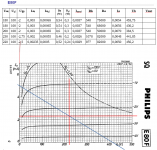
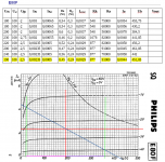
Ua = 190 V ; Ia = 2,35 mA ; Ug = -2,5 V ; Iag2 estimated 0,5 mA ; Ra = 91k Ohms ; Rk = 877 (?) ; Ub = 452 V
Working between 1V < Ug < 4 V. The purple line, at the bottom, are equal. So I imagine low H3 distortion ? But some H2 because I am in the knee at the left ?
Any advantages to lower the Ug2 voltage ? like 70V or 80V ? Can't suppose the curves 🙁
Thank you in advance !
Attachments
Notice you need 3Vpp in to get 200Vpp out. This soes not meet your "200 Vpp output for an input around 2/3 Vpp" goal.
I don't see accounting for LOAD. High-level amplifier design always starts with load. Is it a 10Meg piezo? Or a 470K grid resistor? Or 100K for safe fix-bias? Is the load capacitance <10pFd or over 100pFd? (100pFd is 100K impedance at 16KHz.)
Looking at E80F application info, they only suggest 120Vpp and gain of 200, and this for a very high 0.68Meg load. So dubious.
The design is also dubious from rules of thumb.
Wide audio band pentodes make gain of ~~100, not 300 (200V/0.66V). 300 is possible if load is super light and 5KHz is acceptable, such as driving a cathodyne with large overall NFB.
A tube can usually be designed to give a peak voltage 20% of the supply. Your 200Vpp is 100V peak which suggests a 500V supply at least. Even at this point you may not be "good sounding".
Set Vg2 low (for best voltage gain) and high (for best swing). Run Vg1 as small as possible without going into grid current or knee-cramp. Your #2 design is probably good for 500K loads. I think you need a bigger pentode to drive lower loads; this will usually trade-off voltage gain.
Two cascaded medium-Mu triodes will give gain near 300 and good swing. A high-Mu into a lower-Mu may do better.
Hello,
Thank you for the this reply and thoses informations !
Sorry, I was in my tunnel vision ... head in the schematics. The load is a cathodyne phase spliter.
My objective is a tube amplifier around 25 Watts, a maximum 500 V B+, three stage max.
- Last stage : LL1623 (Zaa = 5.6L Ohms for 8 Ohms) and KT88 (biased at 430 V, 90 mA and Ug ~= -45 ).
- Second stage : cathodyne phase spliter. For the preliminary design, I go with a 6SN7GTB with 110 V on the cathode, 110 V on the anode, and 230 V of swing input. 6SN7GTB biased at 340 V, 10 mA, Ug = -12 V.
- First stage : the amplifier, needs more 200 Vpp out, preferences for 250 Vpp or more. So I was thinking to a pentode designed for audio purpose like the E80F.
Thank you for those crucial detail ! I will retry some loadlines.
Perphaps the pentode was not a so good idea and I would better time to use a triode (or pentode strapped) like 6SL7 or D3A ...
Thank you again.
Regards,
Thank you for the this reply and thoses informations !
Sorry, I was in my tunnel vision ... head in the schematics. The load is a cathodyne phase spliter.
My objective is a tube amplifier around 25 Watts, a maximum 500 V B+, three stage max.
- Last stage : LL1623 (Zaa = 5.6L Ohms for 8 Ohms) and KT88 (biased at 430 V, 90 mA and Ug ~= -45 ).
- Second stage : cathodyne phase spliter. For the preliminary design, I go with a 6SN7GTB with 110 V on the cathode, 110 V on the anode, and 230 V of swing input. 6SN7GTB biased at 340 V, 10 mA, Ug = -12 V.
- First stage : the amplifier, needs more 200 Vpp out, preferences for 250 Vpp or more. So I was thinking to a pentode designed for audio purpose like the E80F.
Set Vg2 low (for best voltage gain) and high (for best swing). Run Vg1 as small as possible without going into grid current or knee-cramp. Your #2 design is probably good for 500K loads. I think you need a bigger pentode to drive lower loads; this will usually trade-off voltage gain.
Thank you for those crucial detail ! I will retry some loadlines.
For sure .... but I would loose my design : three stage, only one pupose for each stage : first amplifier, second phase splitter, third output.Two cascaded medium-Mu triodes will give gain near 300 and good swing. A high-Mu into a lower-Mu may do better.
Perphaps the pentode was not a so good idea and I would better time to use a triode (or pentode strapped) like 6SL7 or D3A ...
Thank you again.
Regards,
For sure .... but I would loose my design : three stage, only one pupose for each stage : first amplifier, second phase splitter, third output.
Perphaps the pentode was not a so good idea and I would better time to use a triode (or pentode strapped) like 6SL7 or D3A ...
Thank you again.
Regards,
Or perhaps you need to work the design through properly. A cascade IS one stage, its just made out of two units.
With the amount of gain you are targeting (0.66:200) and with headroom for feedback as you suggest you want you are pushing it uphill with a pointed stick with your proposed topology and voltage limits.
As earlier comment suggested, you need to consider bandwidth as well as voltage swing.
Rather than stick rigidly to the topology goal and have that drive the circuit design decisions, let the circuit requirements drive the topology decisions. This means being open to different phase splitter and voltage amp topologies. Perhaps even considering dedicated drivers to push the finals around firmly without presenting too much load to earlier stages.
I used to have the design article referred to in this thread - it was a beauty. If I can find it I'll post it. The schematic for the Renard is worth looking through not for specifics as much as for interesting ideas you might consider.
The amp you describe, 45V(47V?) grid bias, needs less than 50V peak per grid to SLAM to full output. You want "more", but unless this is a guitar amp you don't want a lot more (and in a g-amp you need a nice determination of "more" to avoid grid-block and crap-out).
So you need to bring your 0.66V peak input to 50V peak output. Gain of 75 is more possible. Except if you run those big bottles as Pentode you "need" significant NFB to be not-nasty with typical hi-fi speakers. So back to needing gain of 400.
All which occurs to me is a constant-current load on the pentode. Which means another active device. Spoils the conceptual cleanliness. And "another device" is typically best spent as a gain stage, not an active load.
But many ways to skin cats. And in DIY a near-miss can be as fun as any build. Keep sketching.
Hello,
Thank you evryone. You are totaly right ! I complety miss the way the cathodyne work ...... I have think that the cathodyne needs x2 ... wrong ... so wrong.
So now I'm asking my self if I need a pentode at all ... I must restart the calculation with adding a little feedback, around 6 dB.
For exemple a 6SL7 with B+ at 420 V can output 200 Vpp from 3.8 Vpp ....
By the way ... ... I still don't know how to bias a pentode properly 🙁
Hum ... In the next few days I will do a post about the amplifier itself 😉
Thank you again !
- Status
- Not open for further replies.
- Home
- Amplifiers
- Tubes / Valves
- How to bias a pentode - E80F