Curious what the correct balance arrangement should be.
Here's how things are set up
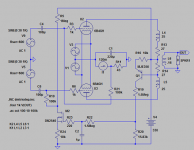
1. Push Pull DHT finals using a shared (center tapped) filament transformer
2. Cathode bias (resistor) connected between center tap and ground
3. A/C heated filaments
Thanks
Here's how things are set up
1. Push Pull DHT finals using a shared (center tapped) filament transformer
2. Cathode bias (resistor) connected between center tap and ground
3. A/C heated filaments
Thanks
No provisions for balancing are possible with the set up you have described above, you must use fairly well matched tubes in this instance.
Thanks.
What's the right way to do this, then. Separate filament transformers ?
FWIW, I do have an interstage transformer splitting phase with dual secondaries (currently tied together at ground potential). I could use fixed grid bias if that would help, though there's still the complication of measuring individual tube bias.
One method I have used successfully to balance push-pull DHTs is to employ a Williamson style bias balance/bias adjustment arrangement, along with small 1 ohm current sampling resistors in the pate leads. Alternatively, I have used the same arrangement without the plate resistors, but with output transformers that featured separate B+ leads for each plate winding. This made it easy to switch a small ma meter in series with each B+ lead to measure current flow. The Heath WM-6 is but one example of amplifiers employing the latter approach's technique. Either of these methods will allow balancing while only needing one filament transformer for the two tubes.
Dave
Dave
Last edited:
The only desperate way to do this would be take adv. of the fact that the DHT grids
are at 0 volts at idle (since you are using a cathode bias resistor and common filament
transformer). You could then apply a small, additive DC input at each grid - using a
potentiometer and resistor network. You could use a 9V battery, as that's as much
trim as you'd need.
Again, this is desperate, because obviously each DHT has a different transconductance, so the moment AC signal is applied to the grids, there'd be AC assymetry about 0V as
well as an "error" AC signal at the cathode bias resistors.... Only for idealistically matched
pairs, would there be a pure DC voltage at the cathode R and no AC signal at all...
If you go read some of Lynn Olson's stuff, this induced error voltage at the shared cathode can actually be dealt with through the "WE Bypass" topology. (See Lynn
Olson's Amity amp)
Most PP transformers are gapped to handle DC imbalances as you describe and perhaps
the solution to your problem is to try the WE bypass capacitor approach, or, need be,
get an output transformer that can take some idle imbalance current, and - as someone else mentioned - try to find tubes more closely matched in gm.
-- Jim
Read this!
Find the section (and schematic) related to the enclosed quotation from Lynn..
Western Electric - Rosetta Stone for Triodes
-- Jim
Find the section (and schematic) related to the enclosed quotation from Lynn..
Western Electric - Rosetta Stone for Triodes
This circuit might be the long-sought "Harmonic Balancer" invented by Western Electric. Although it looks at first blush like feedback, it operates quite differently than the usual overall loop feedback. For one thing, it doesn't do anything at all if the circuit is perfectly balanced ... the AC currents flowing between the center-taps of the two transformers will be zero. It only acts on unbalance currents that flow across the PP stage. In other words, the feedback is fully effective if one tube is pulled out of the circuit, and in practice helps to balance the PP pair of tubes under dynamic conditions. As with the neutralization technique described above, you need to make careful measurements under different drive levels, including deep clipping, to determine the right ratios of capacitors and the voltage divider.
-- Jim
Matched and bypassed CCS in the plate circuits?
Any drop in plate voltage same as 1/Mu drop in grid bias.
To spare such a drop, needs higher B+ voltage to start with...
Any drop in plate voltage same as 1/Mu drop in grid bias.
To spare such a drop, needs higher B+ voltage to start with...
- Status
- Not open for further replies.
- Home
- Amplifiers
- Tubes / Valves
- How to balance pushp pull DHT finals