I have found great posts on this subject in the past but can't find them now. I'm looking for resource info that defines the anomalies and how to correct them.
This was 2v P-P in and about 15v P-P out into 8ohm wire wound resistor (inductive). At about 1k hz.
This was 2v P-P in and about 15v P-P out into 8ohm wire wound resistor (inductive). At about 1k hz.
Attachments
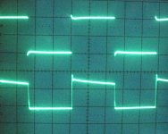
The overshoot is due to a peaking of the high frequency response above midrange gains or the inductance of the load. However, the input shows peaking as well, so perhaps you need to readjust your oscilloscope probes.
The droop is due to lack of low frequency response. Make sure the 'scope is in DC mode.
How much of either would be considered acceptable depends on your standards. You can compute the low frequency point from the speed of the decay of the wave. The fact that only the top of the wave droops implies that the baseline is in limiting.
I have never been a fan of square wave testing, instead preferring a frequency sweep.
It is helpful to remember that a square wave is actually a pulse and should be treated as such. When using square waves it is important to terminate the output of your generator in it's characterstic impedance. Typically 50 or 600 ohms for most makes. This should be done at the far end of the coaxial interconnect cable where it meets the input of the amplifier under test. This is necessary to prevent overshoot and other anomalies. Coaxial feed-thru terms are the best, but lacking that, temporarily tack soldering a ½ watt carbon resistor of the proper value across the amplifier's input will serve just as well. Learning and becoming familiar with square wave testing will provide a wealth of information in a single test over plain sine waves.
- Status
- Not open for further replies.