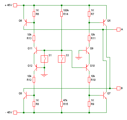
hello,everyone! the circuit diagram is to achieve the following functions
1 : When the switches(s1,s2,s3) are off, output A is 45v,output B is -45v
2 : when you turn on the s1,the q1 and q2 are off,so the output A is not 45v,and output B is not -45v
3 : when you turn on the s2 (s1,s3 is off) , q5 is on ,so output A and output B are short circuits
4 : when you turn on the s3 (s1,s2 is off) output A is -45v,and output B is 45v
the logic circuit is no problem On the whole,but it should be improved because of high import input voltage.i am not good at modern circuit ,and i do not know how to add some protection circuits
thank you for helping me ,thanks!
An externally hosted image should be here but it was not working when we last tested it.
Last edited:
i checked it ,thank you for having a look and giving me some suggestions!?
Did you check what you posted?
I do not want to be unkind, but there are so many things wrong with this "circuit" that my advice to the OP is: use some DPDT switches to get where you need to go. E
I do not want to be unkind, but there are so many things wrong with this "circuit" that my advice to the OP is: use some DPDT switches to get where you need to go. E
a lot of things wrong ?
but i also need the swithes times for about 1us,and the DPDT can not reach it
I don't know what you are protecting against. but a lightning surge would blow right through the transistors from one end to the other. Also, on the subject of protecting against shorted output wires, you are not even sensing output current. ????
I don't know what you are protecting against. but a lightning surge would blow right through the transistors from one end to the other. Also, on the subject of protecting against shorted output wires, you are not even sensing output current. ????
thank you for concerning about this problem .
Here is a start, with just S1 and S3.
When both switches are open, R14 pulls the voltages on the bases of Q11 and Q10 up. Q11 is switched on so current flows through Q11 and Q12 to switch on Q6 and Q8. Q10 is switched off, so no current flows through Q10, Q9, Q5 or Q7.
When S3 is closed, R15 pulls the voltages on the bases of Q11 and Q10 down. Q10 is switched on so current flows through Q9 and Q10 to switch on Q5 and Q7. Q11 is switched off, so no current flows through Q11, Q12, Q6 or Q8.
When S1 is closed, the bases of Q10 and Q11 are both grounded, so both are switched off and no current flows through any of the transistors.
Switch 2 may be difficult.. ...
switch 1 and switch 3 are solved by godfrey ( a member of diyaudio),but lack the swith 2
A and B only have to be shorted to each other, no must they both be shorted to ground. of course ,a relay is allowed ,but i I never used,if you can solve the switch 2 problem by transistors,i can understand easily.
would you help me solve this problem ,thank you very much
a lot of things wrong
One thing I see right away, the bases should be shorted to the negative rail.
Protection from what? Has this anything to do whit audio?
Overcurrent protection would be nice. Perhaps that's what he meant. That's easy to add, but the basic functionality should be sorted out first.Protection from what?
First he shows push-buttons, then he says microsecond switching times are required.😕
p.s. I only found this thread now. I was previously trying to help in his other thread here: http://www.diyaudio.com/forums/power-supplies/211828-protection-circuits-swith-circuit.html. Meh - duplicate threads.

- Status
- Not open for further replies.
- Home
- Source & Line
- Analog Line Level
- how to add protection circuits (swith circuit)