It should be applied from the load terminal to the grid of V3A, the 0.1u cap modified to a RC (27k/1uF).
Herews schem https://www.vintagehofner.co.uk/britamps/watkins/schematics/westminmk9.html if anyone can show me thanks!
No, not the way you draw it.
Add a 4.7k resistor from the 100nF to ground, then add a 100k resistor from the secondary of the output transformer to the point between the 4.7k and the 100nF. Play with the 100k and 4.7k to find the sweet spot (the amp will then have a fixed presence control).
Add a 4.7k resistor from the 100nF to ground, then add a 100k resistor from the secondary of the output transformer to the point between the 4.7k and the 100nF. Play with the 100k and 4.7k to find the sweet spot (the amp will then have a fixed presence control).
Thanks, so theres no need to also go into bottom of tail res..? Seen a few diagrams that do this..
Last edited:
Tail is at high voltage, going there you short it to ground.
If the amps squeals when you turn it on, you need to reverse the connections from PI to output tubes or from output tubes' anodes to the output transformer, or secondary winding (ground and feedback tap).
If the amps squeals when you turn it on, you need to reverse the connections from PI to output tubes or from output tubes' anodes to the output transformer, or secondary winding (ground and feedback tap).
I'm reading from this guy - https://robrobinette.com/5F6A_Modifications.htm#Long_Tail_Pair
He goes into tail and shunt cap...
He goes into tail and shunt cap...
Why doesnt someone just download the schematic, run it into paint and upload it to here with the wiring I need....
Mines a pcb board, it's confussing as its all running to ground separately
Mines a pcb board, it's confussing as its all running to ground separately
The simply way is to take a signal form one end of the secondary of OT by the resistor to a pin 3 of V1.
What you have to check is the phase of the FB signal.
From schematic you have only one secondary so it will be easy to find the right connection simply inverting the terminal.
You can also use a 10k resistor + in series a trimmer of 50 Kohm configured as reostat, in this way you can check also the sensitivity that will goes down by FB
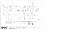
A simply diagram
At the beginning, with the resistor added, if you ear a noise same a rumble ( power off quick the amp) you have to reverse the connection of the point a and b
Do you have a minimum of test equipment?
Bye
Walter
What you have to check is the phase of the FB signal.
From schematic you have only one secondary so it will be easy to find the right connection simply inverting the terminal.
You can also use a 10k resistor + in series a trimmer of 50 Kohm configured as reostat, in this way you can check also the sensitivity that will goes down by FB
A simply diagram
At the beginning, with the resistor added, if you ear a noise same a rumble ( power off quick the amp) you have to reverse the connection of the point a and b
Do you have a minimum of test equipment?
Bye
Walter
Attachments


Why doesnt someone just download the schematic, run it into paint and upload it to here with the wiring I need....
Mines a pcb board, it's confussing as its all running to ground separately
The simply way is to take a signal form one end of the secondary of OT by the resistor to a pin 3 of V1.
What you have to check is the phase of the FB signal.
From schematic you have only one secondary so it will be easy to find the right connection simply inverting the terminal.
You can also use a 10k resistor + in series a trimmer of 50 Kohm configured as reostat, in this way you can check also the sensitivity that will goes down by FB
A simply diagram
At the beginning, with the resistor added, if you ear a noise same a rumble ( power off quick the amp) you have to reverse the connection of the point a and b
Do you have a minimum of test equipment?
Bye
Walter
Attachments
The simply way is to take a signal form one end of the secondary of OT by the resistor to a pin 3 of V1.
Absolutely NOT!!
this way you insert in the nfb loop an equaliser and a volume pot!!
The way to implement the nfb is the one I wrote.
Absolutely NOT!!
this way you insert in the nfb loop an equaliser and a volume pot!!
don't worry.
Walter
I do not, but you should modify your post to avoid other newbies following your suggestion and so make mistakes.
again, don't worryI do not, but you should modify your post to avoid other newbies following your suggestion and so make mistakes.
no mistake.
and the trimmer as the only function to set a proper level of FB; better is the use of some test equipment
Walter
#3 is correct, with the volume and tone control out of the loop.
Adjust the cap to the desired frequency response.
Adjust the cap to the desired frequency response.
- Home
- Live Sound
- Instruments and Amps
- How to add NFB