I agree with that recommendation, your XLR connections are nothing more than unbalanced through an XLR connector, not balanced at all. Connection through an XLR does not automatically a balanced connection make. 😀
Modern ones have XLR inputs in addition to the RCAs. I do not know what they do internally with the XLR inputs.
Attached stock photo from the McIntosh MC-275 owner's manual showing balanced inputs.
The sensitivity is rated at 1.7V for unbalanced and 3.4V balanced which leaves me suspecting it is actually just an unbalanced input switched between RCA and XLR sockets in which case there really is no point to using it in this application.
Attachments
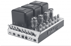
The new MC275 is balanced from the XLR connector all the way to the speaker posts. As Audiowise mentioned, there is a common cathode triode front section that inverts the non-balance input.
Last edited:
I see the R13 will be preamp output impedance not the inner resistance of output stage. It is usually 600R
If I use output transformer, the prim and second impedance will be what?
I have a pair of Lundahl LL9305 output transformer and it is 1+1:1.6+1.6, is it OK?
I have a pair of Lundahl LL9305 output transformer and it is 1+1:1.6+1.6, is it OK?
I would try them at 1+1:1.6 (parallel the secondary). Top of primary to the output capacitor, bottom of primary to ground. Ground the internal shield through a .01uF cap and add a switch to short that cap out to the preamp chassis ground (ground lift). Top of the parallel secondary to pin 2, bottom to pin 3, pin 1 to the shield. Gain and Zout will both go down a bit. You might need to play with the value of the output capacitor.
You might also take the opportunity to lower the 680 ohms cathode bias resistor. As is, it is choking the cathode follower. I would try something around 300 ohms. This will give it more output current (Iout).
Last edited:
Analog Devices SSM 2142 Balanced Line Driver
Analog Devices makes a great chip for balanced line driving. Very easy to use and works great!
http://www.analog.com/media/en/technical-documentation/data-sheets/SSM2142.pdf
Analog Devices makes a great chip for balanced line driving. Very easy to use and works great!
http://www.analog.com/media/en/technical-documentation/data-sheets/SSM2142.pdf
The cheapest and easiest way to convert the output to balanced is to copy AN003 figure 2.4 A Simple Alternative.
This was adopted by B.Putzeys in his balanced volume control.
If you need to spend money, then you can adopt figure 2.2 using the output transformer. But note that "BEST" is adopting figure 2.3 to FIX the input stage.
And you don't need the FIX if the Receiver is already balanced and you adopt figure 2.4
Attachments
Last edited:
This is what I thought too, until I saw the stupidity employed by McIntosh in the new version of this amplifier.The cheapest and easiest way to convert the output to balanced is to copy AN003 figure 2.4 A Simple Alternative.
Not inexpensive,but if you own a C22,this may not be a consideration🙂
Buy a pair of these and build them into a dedicated enclosure with RCA ins and XLR outs. No need to modify the pre,and if you don't like the result,you can easily sell them on later. Follow the included schematic.
http://www.jensen-transformers.com/wp-content/uploads/2014/08/jt-10k61-1m.pdf
Buy a pair of these and build them into a dedicated enclosure with RCA ins and XLR outs. No need to modify the pre,and if you don't like the result,you can easily sell them on later. Follow the included schematic.
http://www.jensen-transformers.com/wp-content/uploads/2014/08/jt-10k61-1m.pdf
- Status
- Not open for further replies.
- Home
- Amplifiers
- Tubes / Valves
- How to add balance output to C22