can anybody tell me how to get very good damping factor for LM3886 amp like arround 500-1000
thanks,
Ken
thanks,
Ken
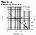
the (excess) loop gain reduces the open loop output impedance of a feedback amp
the loop gain falls as frequency increases
there may not be enough loop gain to reach damping factors of 1000 with 4-8 Ohm loads at KHz with most chip amps
the loop gain falls as frequency increases
there may not be enough loop gain to reach damping factors of 1000 with 4-8 Ohm loads at KHz with most chip amps
Place the chip amp inside the feedback loop of a high quality op-amp. This increases the overall loop gain, reducing distortion to vanishing levels and should improve DF as well. The technique requires putting a phase lead network and some attenuation between the two amps before applying global feedback and the miniumum stable gain is increased. It described how to do this some 15 years ago (or was it 20?) in an old issue of Radio-Electronics using an LM1875.
Interesting question but is it necessary really? Isn't better than 50-100 high enough? Maybe it's a better idea to put the amp very close to the speaker instead. 
I think that use of a good quality high cap regulated supply would help a lot as many amplifiers can't really take advantage of a low output impedance because supply voltage drops under load thus ruining DF.
can anybody tell me how to get very good damping factor for LM3886 amp like arround 500-1000
the (excess) loop gain reduces the open loop output impedance of a feedback amp
the loop gain falls as frequency increases
there may not be enough loop gain to reach damping factors of 1000 with 4-8 Ohm loads at KHz with most chip amps
JCX gives a very good hint. DF cannot be made higher (at a certain frequency) unless there is excess OL gain to be burned at that frequency. If there is no gain, no possibility of highering DF/lowering output impedance.
Maybe if you measure DF at 100hz, you already get that 100's of DF with ordinary gainclone CCT?
You can see OL decreasing steeply with frequency
Attachments
Considering that the DC resistance of the driver is in series with the back EMF of said driver, what does it matter if the output impedance of the amplifier is 1 ohm, 0.1 ohm, 0.001 ohm, etc.
It doesn't matter!
As a practical matter, if the DF is below about 20 or so it affects the Qes of the driver, and thus the Qts. In general, box size is proportional to the square of Qts, so it begins to make a bit of a difference in this case.
It doesn't matter!
As a practical matter, if the DF is below about 20 or so it affects the Qes of the driver, and thus the Qts. In general, box size is proportional to the square of Qts, so it begins to make a bit of a difference in this case.
In most practical cases the damping factor will most probably be controlled by the speaker cable and connection resistance. This can very easily total up to 0.1 to 0.2 ohms . So a damping factor of 100 and larger in the amp should not make any significant difference to the performance.
"In most practical cases the damping factor will most probably be controlled by the speaker cable and connection resistance"
What part of "the DC resistance of the driver is in series with the back EMF of said driver" didn't you understand?
The 0R2 of the wire, connections, and amplifier output impedance is trivial in comparrison with the 6R0 DCR of the voice coil .
What part of "the DC resistance of the driver is in series with the back EMF of said driver" didn't you understand?
The 0R2 of the wire, connections, and amplifier output impedance is trivial in comparrison with the 6R0 DCR of the voice coil .
DJK, your 'tone' isn't right !
Anyway , here is an experiment for the others.
Connect any good ss amp to a speaker with a reasonably large woofer . 6.5 to 8 inches would do.You could use a bare driver also.
Add a 4 ohm or 10 ohm resistor in one of the speaker leads. A small wattage resistor is enough , even a 1/4 watt will do.
Now tap the woofer cone of the speaker . See how the cone responds ( and sounds).
Now remove the resistor and connect direct to the amp and repeat the process . Does the cone appear 'controlled' -- damped ?
Needless to say the power amp must be powered up.
Cheers.
"DJK, your 'tone' isn't right !"
Maybe I'm tired of people that repeat the old 'damping factor' myth without examining what is really going on.
Like here for instance.
If a nominal 8R loudspeaker has a DCR of 6R, it will generally have an impedance minimum of around 7R. So the real DF is 1.167
Now we add 10R (your value). The DF is now 0.4375, a big difference between that and 1.167
The DF difference between an amp with 0R008 output impedance (an advertised DF of 1000) and an amp with 0R08 output impedance (an advertised DF of 100), is 1.165 vs 1.151
Now, do you really think a DF difference (real world) of about 1.2% can be compared with your example of a difference in DF of about 267% ?
I own several solid state amps with an advertised DF of 14, stock they sound 'warm'. In a listening test with another brand with a DF of 400 it was judged 'thick', or 'slow' sounding. Must be the DF?
Think again.
Adding about $4 worth of bypass caps to the amp with the DF of 14 totally changed the sound in the bass. Now in a listening test with the same DF of 400 amplifier, the DF of 14 amplifier now sounded 'tighter' in the bass, and had more 'slam'.
How could this be?
Hi DJK,
I do get your point and am well aware that the coil DCR is in series with the motor circuit.
However the effect of an external resistance is very significant.
If you take a moving coil meter and short it leads and shake the meter you will hardly see it's needle move. Add a resistance equal to the coil resistance between the terminals and shake the meter. The needle will move significantly .
The loudspeaker will behave the same way. Check it out.
I agree with all else you say but disagree when you say that the external resistance doesn't matter at all.
Additionally I do agree that very high damping factors in the amp will be lost by other series resistances that will swamp the amps low z out.
What exactly did you mean by using a bypass cap in the amp ? What value and where ? Parallel with the output ?
"Add a resistance equal to the coil resistance between the terminals and shake the meter. The needle will move significantly . "
So what?
This is the same example you gave before, an un-realistic shunt impedance.
What I am saying is it does not matter if you short the speaker with 0R008 or 0R08, typical values or amplifier output impedances.
"What exactly did you mean by using a bypass cap in the amp "
Power supply bypass and caps in the signal path too. Usually between 22µF~100µF on the main supply, and 0.1µF for coupling and feedback caps.
- Status
- Not open for further replies.
- Home
- Amplifiers
- Chip Amps
- How to achieve very high damping factor with LM3886