Hello my dear friends! I'm a newbie here... 😊
I just designed something that I believe would find me the finest lows. I made my own theory on how it measures in propotion to the speaker. I sketched it below just for reference. However, much interesting will be my silly theory.
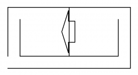
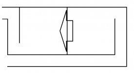
I make two rooms of same volume by centering my speaker, what theoretical here is, that volume divided by three (to find how long/wide/tall) is equal to the diameter of the speaker plus two inches, for example, if I choose a 10 inches speaker the rooms will be 1728 cubic inches each. Now my slot port comes, its width is equal to quarter the size of the room volume divided by three, back to that example, 1728"/3 = 12" and 12"/4 = 3" or the port width.
To better understand what I explained here, refer to the sketch below as you read these calculations.
I'm pleased to know if I'm silly enough to absolutely ruin my project, because this funny thought is mine and obviously I'm not a subwoofer maker.
But, my friend who is a subwoofer maker is very excited about my design, so I'm eager to get your opinions.
Thanks in advance... 🙂
I just designed something that I believe would find me the finest lows. I made my own theory on how it measures in propotion to the speaker. I sketched it below just for reference. However, much interesting will be my silly theory.
I make two rooms of same volume by centering my speaker, what theoretical here is, that volume divided by three (to find how long/wide/tall) is equal to the diameter of the speaker plus two inches, for example, if I choose a 10 inches speaker the rooms will be 1728 cubic inches each. Now my slot port comes, its width is equal to quarter the size of the room volume divided by three, back to that example, 1728"/3 = 12" and 12"/4 = 3" or the port width.
To better understand what I explained here, refer to the sketch below as you read these calculations.
I'm pleased to know if I'm silly enough to absolutely ruin my project, because this funny thought is mine and obviously I'm not a subwoofer maker.
But, my friend who is a subwoofer maker is very excited about my design, so I'm eager to get your opinions.
Thanks in advance... 🙂
Attachments
At least the post is now in the appropriate section of the forum!
I would disregard the original one in the 'Construction Tips' section.
I would disregard the original one in the 'Construction Tips' section.
I'm extremely sorry dear, I got to know the right section later, tried to delete the other thread, but wasn't allowed...
Interesting.
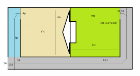
That box can be simmed using Hornresp's TH sim, with parameters entered as illustrated in the attached image. As a variation, you could move the vent entrance to the rear cabinet a bit, allowing L12 to be varied, which could be useful in nulling out any vent resonances predicted by the model.
If I have some time this weekend, I'll put together a BOXPLAN workbook that can be used to design the layout, and it will output a corresponding Hornresp sim.
Attachments
It almost is a 6th order bandpass box. WinISD can simulate it too. Usually the chambers have different air volumes, with the one with the lowest tuning (longest port, the one on the right) being larger than the other.
Interesting.
That box can be simmed using Hornresp's TH sim, with parameters entered as illustrated in the attached image. As a variation, you could move the vent entrance to the rear cabinet a bit, allowing L12 to be varied, which could be useful in nulling out any vent resonances predicted by the model.
If I have some time this weekend, I'll put together a BOXPLAN workbook that can be used to design the layout, and it will output a corresponding Hornresp sim.
Bro, your response is highly appreciated. This is the 1st time I'm presenting this to someone, so I'm really happy that you're interested about this. It'd be a great help if you'd do that thing at your leisure time.
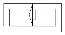
BTW, do you suggest the port moving like in this attached image?
Thanks once again bro...
Attachments
It almost is a 6th order bandpass box. WinISD can simulate it too. Usually the chambers have different air volumes, with the one with the lowest tuning (longest port, the one on the right) being larger than the other.
You've come to a really good point. My question is, does the rear chamber which is and should be tuned to the lowest (in the 6th order bandpass theory) need to be larger when the port is longer, in other words, is the port alone not capable of being tuned to the lowest with its length while both chambers are the same in volume, just as the design I sketched here...?
For a 6th order bandpass enclosure, each chamber has (1) a tuning frequency and (2) an air volume. Increasing the port length can bring the tuning frequency to the desired value, but has no influence on the air volume.
Try simulating a 6th order bandpass enclosure in WinISD to see the effect of increasing or decreasing the air volumes.
Try simulating a 6th order bandpass enclosure in WinISD to see the effect of increasing or decreasing the air volumes.
For a 6th order bandpass enclosure, each chamber has (1) a tuning frequency and (2) an air volume. Increasing the port length can bring the tuning frequency to the desired value, but has no influence on the air volume.
Try simulating a 6th order bandpass enclosure in WinISD to see the effect of increasing or decreasing the air volumes.
Yeah, WinISD has to decide it, you meant perhaps both chambers would remain the same volume after simulation right?
BTW, I'd like to get your opinion about both airflows exitting at the same point.
Maybe I am not reading this correctly, but... this looks like the front chamber is coupled to a short port, the rear chamber to a long port. As this is is intended for low-frequency sound, I'd think that the sound appearing at the exits of the two ports are pretty much 180° out of phase. Since both ports exit at the same spot, their outputs will largely cancel each other.
Yes, the chambers / ports are probably not tuned to the same frequencies, so the cancellation will not be 100%, but still...
Yes, the chambers / ports are probably not tuned to the same frequencies, so the cancellation will not be 100%, but still...
Maybe I am not reading this correctly, but... this looks like the front chamber is coupled to a short port, the rear chamber to a long port. As this is is intended for low-frequency sound, I'd think that the sound appearing at the exits of the two ports are pretty much 180° out of phase. Since both ports exit at the same spot, their outputs will largely cancel each other.
Yes, the chambers / ports are probably not tuned to the same frequencies, so the cancellation will not be 100%, but still...
I'm also quite uncertain about this, my point is the same you mentioned, if the chambers are tuned at different freqs, how much would the outputs cancel each other out...? 🙄
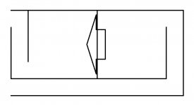
BTW, have you noticed the change I made to the design later in the reply to Brian Stelle? If not, here it's...
How about this?
Attachments

I can see you did a minor change to the exit of the ports. However, this will be irrelevant, since the wavelengths of the frequencies involved are waaaaay larger than this little mod.
I can see you did a minor change to the exit of the ports. However, this will be irrelevant, since the wavelengths of the frequencies involved are waaaaay larger than this little mod.
True...
What do you think of these two?
Attachments
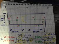
Not sure if this is what youre asking? But i have built the green ‘B’ with red and green version of ‘A’ .
If this isnt relevant, just ignore it
OMG, how is that calculated, have you followed my theory in your calculation? Dude, first of all I think you missed the driver part, magnet side should be inside A. 😱
I dunno why the motor side matters in oscillation (overall), but i used isobaric on the green version.
I do think the red is ‘workable if you offset the 80cm or create the phase change as needed. 320 and 80 work as a compounded offset combo.(maybe?( a stub is useful in a strategic location...
Useful if an expanding path is chosen.. it seems
I do think the red is ‘workable if you offset the 80cm or create the phase change as needed. 320 and 80 work as a compounded offset combo.(maybe?( a stub is useful in a strategic location...
Useful if an expanding path is chosen.. it seems
Last edited:
I dunno why the motor side matters in oscillation (overall), but i used isobaric on the green version.
I do think the red is ‘workable if you offset the 80cm or create the phase change as needed. 320 and 80 work as a compounded offset combo.(maybe?( a stub is useful in a strategic location...
Useful if an expanding path is chosen.. it seems
But, an isobaric environment in general, as far as I know, is infinite in space on the motor side unlike what you suggest here right?
- Home
- Loudspeakers
- Subwoofers
- How silly can this be...?