I have designed a 1600 watt amplifier module.
I worked out I need a 0.1 degree/Watt heat sink.
How much smaller could this heat sink be if I kept it cool using a fan ?
I worked out I need a 0.1 degree/Watt heat sink.
How much smaller could this heat sink be if I kept it cool using a fan ?
I have designed a 1600 watt amplifier module.
I worked out I need a 0.1 degree/Watt heat sink.
How much smaller could this heat sink be if I kept it cool using a fan ?
Bear in mind that the rating is only for a uniform loading over the entire heat sink surface.
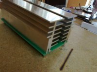
Here are some sinks that I've used with fans. They're big.
Standard Bonded Fin - heat sinks
Last edited:
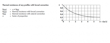
The sink must be designed for a fan, then you can get about a 5:1 improvement.
Agreed. The maximum improvement is to reduce the thermal resistance with 80%. You need more than 5m/s air speed for it. So powerful fan is necessary.
This picture comes from the Fischer catalogue.
Sajti
Attachments
Last edited:
I would guess at almost 10:1 improvement using a fan.
A fanned heatsink is far better than 10:1 might imply.
i.e. take the fan off a fanned sink and the heatsink capability mat fall to only 5% of the fanned rating.
A fanned heatsink is far better than 10:1 might imply.
i.e. take the fan off a fanned sink and the heatsink capability mat fall to only 5% of the fanned rating.
It also depends on the design of the heatsink, some of the better ones require very high pressures to get the airflow rate which can argue for blowers rather then fans (Blowers are generally quieter anyway).
Very careful optimisation of the interface between the heatsink and the device also pays huge dividends at this level, most extruded heatsink you buy has a mounting surface that is anything but flat and you can make a huge difference by running a fly cutter over the mounting area to mill away the height variations.
The RF guys like to fit a copper heat spreader under the power devices (Sometimes soldered to the device), this serves to increase the contact area and thus lower the interface thermal resistance.
Don't forget that lower interface thermal resistance directly equates to being able to run the heatsink hotter for a given junction temperature, so allowing a smaller heatsink or quieter fan.
For a project with similar power dissipation requirement I used one of these http://www.farnell.com/datasheets/1692180.pdf which are compact for what they do and come with the mating face allready milled flat.
Regards, Dan.
"I would guess at almost 10:1 improvement using a fan."
So the manufacturer's data in post #4 is wrong?
"i.e. take the fan off a fanned sink and the heatsink capability mat fall to only 5% of the fanned rating. "
Not valid.
Forced air on a natural convection design will not yield anywhere near 10:1, and a forced convection design (with no fan) will suffer in comparison with a similar sized natural convection design.
A pure copper tunnel (like a Crown MA5000VZ) with direct metal mounted devices will give your 10:1 figure (easily), a natural convecion design with insulators under each device will not.
I agree with djk. The only thing is that any heatsink acting like in the diagram.
The best solution would be to avoid any solution which worse the heat transfer, such the insulator between the device and the heatsink.
See my solution on the picture. The heatsink will be insulated from the chassis, and the output devices will be mounted without insulation. The heatsink will act as power supply rail too.
Sajti
Attachments
The best solution would be to avoid any solution which worse the heat transfer, such the insulator between the device and the heatsink.
Depends on the type of insulator used.
Keratherm red does 0.07C/W for a TO-264, 0.06C/W for a TO-3, 0.05C/W for an MT-200 package.
Your suggestion does not yield zero Rcs, but lots of compromises and constraints instead (been there, done that)
To put some numbers into it [tm] , the excellent Aavid site posted above (thanks Rayma 🙂 ) includes a design tool which factors in air speed:
- heatsink design tools
Do your Math 🙂
Suggesting numbers pulled out of thin air without justifying them won't carry you very far 🙁
By the way, did you answer my questions about this amp in your other post? (number and type of transistors, schematic, etc.).
Thanks.
- heatsink design tools
Do your Math 🙂
Suggesting numbers pulled out of thin air without justifying them won't carry you very far 🙁
By the way, did you answer my questions about this amp in your other post? (number and type of transistors, schematic, etc.).
Thanks.
To put some numbers into it [tm] , the excellent Aavid site posted above (thanks Rayma 🙂 ) includes a design tool which factors in air speed
Yes, we've been using Aavid sinks for prototypes for years, especially the larger bonded fin types with integral fan mounting.
They have large beautifully machined mounting surfaces, and can be reused over and over. Pcbs can also be mounted on the side brackets of the sink assembly.
Standard Bonded Fin - heat sinks
- heatsink design tools
Depends on the type of insulator used.
Keratherm red does 0.07C/W for a TO-264, 0.06C/W for a TO-3, 0.05C/W for an MT-200 package.
Your suggestion does not yield zero Rcs, but lots of compromises and constraints instead (been there, done that)
Agree with You. However I want to avoid to pay same price for the insulator, as for the output device (TOP-3).
Mounting without insulator means something 0.01-0.05 depending by the quality of the heatsink.
Sajti
If you look at the RS online catalogue most of the bigger heatsinks have data sheets which show you exactly how they behave in various situations.
- Status
- Not open for further replies.
- Home
- Amplifiers
- Solid State
- How much smaller can heatsink be if fan used ?