Maybe that is because you haven't explained the point in simple enough terms for someone with an EE PhD to understand?waltube said:In my opinion you haven't understood the point
You made a claim. You then posted graphs which you said backed up your claim. You now won't tell us how they back up the claim? That is fine by me; I will just ignore your claim as it remains unsubstantiated.
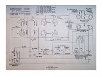
1934 Webster amplifier
The first version (MKI) of this amplifier came with two 30 uF electrolytic capacitors. Few of them were made, as MKI was replaced within the same year with MKII that had two 6 uF PIO capacitors and extra choke. MKIII, which came in 1936, retained the same configuration of power supply as MKII, but 2A3 tubes were replaced with 6V6G connected with cathode feedback OPT winding.
I have all 3 versions. MKII sounds much better than MKI. The only difference between them is power supply. I guess engineers quickly figured out that extra expense of PIO capacitor block and additional choke is worth it as it gives substantial sound improvement.
Attachments
Here's a primer on capacitors. The frequency characteristics might be useful: http://www.cde.com/resources/catalogs/AEappGUIDE.pdf
"Sounds much better" is a subjective statement of preference, not an objective statement of sound reproduction fidelity. The amp appears to have no global feedback, so the gain will vary with supply rail voltage so a PSU with highish subsonic output impedance will give some gain pumping which some may misperceive as being better dynamics.sser2 said:I have all 3 versions. MKII sounds much better than MKI. The only difference between them is power supply. I guess engineers quickly figured out that extra expense of PIO capacitor block and additional choke is worth it as it gives substantial sound improvement.
470ufd/450volt caps are dirt cheap over here, i got over a hundred new caps waiting to get used, so i use them, but i do not go around telling how good they are...who is to stop me?
On a diagram of the continuos power ( red line) and dynamic power (blue line) is possible to see the differences that comes with the help of a robust power supply , 510 joule each channel.
The test is done with changing the load with a specific sw and AP1 that take a care of distortion, in this case 2% maximum.
On 8 ohms the difference is about 15 watts but on 4 ohms is around 100 watt
Next time I will take a imagine of scope.
Walter
Maybe you should explain the difference between continous and impulsive signals. Are they signals of different nature? Some (probably most) people think that impulsive signal is just the peak of a sinusoid....
On post nr. 20 I described the type of test, the signal are, in both test, 1 Khz sino.
xDF96
I wrote my opinion.
I also told you that on VTL book by David Manely you can find some info around supply; he was more important , as engineer, than me, of course.
I will be back next days
Walter
xDF96
I wrote my opinion.
I also told you that on VTL book by David Manely you can find some info around supply; he was more important , as engineer, than me, of course.
I will be back next days
Walter
On post nr. 20 I described the type of test, the signal are, in both test, 1 Khz sino.
Then it might not be just related to power supply only. If the secondary load drops from 8 to 4 ohms then the primary impedance will be 1/2 and the driver might be able to push the power tubes much further as grid current might be much less severe.....
In fact I wrote that there is also the capability of the tubes to delivery current but if you haven't enough reservoir will be not possible to get these results.
In this project, due to the limit of space, I used a potted supply trafo of 500VA; if I use a 1KVA ( less rdc) with the same capacitance I will have a better results both for rms and impulsive.
Walter
In this project, due to the limit of space, I used a potted supply trafo of 500VA; if I use a 1KVA ( less rdc) with the same capacitance I will have a better results both for rms and impulsive.
Walter
The reservoir cap needs to have enough capacitance to keep going until the next charging pulse comes along. To determine this you need to do a ripple calculation. What is new/different/esoteric about this?
If I may speak for the others, you're considering DC only. I think one must regard the audio signal as well, along with the supply ripple. In smallish ampifiers this might be benign, in high current amps it plays a role. High current amps have low Ra.
Last edited:
Greetings,
I saw a $$$$ amp that had an optional HV cap bank, no values mentioned but from the looks I'd say it must have been over 2000 µF (2mF). Of course they claimed all sorts of benefits, which made me wonder: how much capacitance is useful for an output stage, say a 100W PP? I've gone up to 500 µF, but is there a point in using more?
Thanks in advance.
There really isn't benefits in a standard circuit. Some people add too much capacitance without really understanding why.
There could be instances where you would want 2000uF in a power supply section for a tube amp. However, it wouldn't be the simple pi filter designs that are commonly used.
Ditto for the foil cap bypass, it always seems to pop up in these sort of discussions, so for a different POV, see Capacitor Characteristics about 2/3 of the way down.
I am considering whatever takes charge out of the capacitor. As a general rule if a capacitor is big enough to have low ripple voltage at 100Hz then it will be big enough to have even lower signal voltage at 1kHz.disco said:If I may speak for the others, you're considering DC only. I think one must regard the audio signal as well, along with the supply ripple. In smallish ampifiers this might be benign, in high current amps it plays a role. High current amps have low Ra.
In some cases this can raise the supply impedance, especially if low ESR electrolytics have been used. Of course, if the resultant sound degradation is audible it may be misperceived as an improvement.hpeter said:Every wet cap needs foil cap (pp) bypass. Lowers the supply impedance at higher f.
- Status
- Not open for further replies.
- Home
- Amplifiers
- Tubes / Valves
- How much PS capacitance for PP output stage?