Greetings,
I'm trying to figure out my first tube-rectified PS and can't reconcile between the two pieces of info that I have. These pieces are in the drawing below.
The upper portion depicts the part of the schematic, the lower is from the 6X4 rectifier spec.
The first shows that two tubes are used for the full-wave rectification; the spec has only one tube for the same application. "Audio Classroom" series in Glass Audio says, "When two rectifiers (or two halves of a dual rectifier) are used in full-wave rectification ...] - so I guess both scenarios are possible.
So my questions are:
1. How can one tell whether a tube is a dual rectifier? If it has two plates? Or if the tube spec states "full-wave recitifier" it means it is also a "dual rectifier"?
2. If 6X4 is a dual rectifier why would somebody put two of them in PS instead of one?
3. How many is really needed - one or two?
4. While on the topic of the spec vs schematic: for 6X4 the filter capacitor is indicated max 40uF, but the schematic uses 100uF - what are the real limits? Can, let's say, 470uF be used?
Thanks!
Attachments
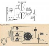
The first diagram shows two 6X4 rectifier in parallel, a strange combination, probably done because the current was too high for a single one. Each rectifier is basically a double diode, you can use two silicon diodes to replace it. This topology, with the centre tap of the transformer connected to ground, is called full-wave rectification.
The second diagram shows 6X4 in typical operation, with a max ouput current of 70mA.
What is the current in your schematic? If it is higher than 70mA you might want to use a single EZ80 or EZ81 rectifier, much the same sort of thing except Ez80 will take 90mA and EZ81 150mA.
In answer to your specific questions:
1) Most tube rectifiers contain two diodes joined at the cathode. (two anodes, 1 cathode.)
2) see above.
3) whatever is necessary for your max current.
4) I wouldn't go above 40uF for a 6X4, but for two in parallel, 100uF is probably ok. For EZ80 and EZ81, use 47uF.
Keep in mind that in a CLC power supply there is a lot of filtering, and a 40u-10H-40u filter will give very very good filtering in most cases, for currents up to several hundred mA. Adding more capacitance won't do very much and will shorten the tube's life.
I haven't seen dual rectifier but usually Full wave rectifier, a FW rectifier tube has 2 isolated anode plates1. How can one tell whether a tube is a dual rectifier? If it has two plates? Or if the tube spec states "full-wave recitifier" it means it is also a "dual rectifier"?
The only technical reason is to take care of more current then one tube can handle, this has been done before but usually it is recomended to use low value resistors in series with each tube in order to avoid that one tube is overloaded if it would take care of more current.2. If 6X4 is a dual rectifier why would somebody put two of them in PS instead of one?
I think it is better to use a larger rectifier tube if one is not enough, if one is enough currentwise it should be OK to use one, I use 6X4 almost on max ratings in my preamp but experience no problems whatsoever3. How many is really needed - one or two?
The max value of capacitance is choosen in order to limit peak current, if a series resistor is used then almost any cap value can be used with big enough resistor but it is a very inefficient way to design like that. By using PSUD the peak current can be simulated and appropiate resistor value selectedWhile on the topic of the spec vs schematic: for 6X4 the filter capacitor is indicated max 40uF, but the schematic uses 100uF - what are the real limits? Can, let's say, 470uF be used?
Regards Hans
< What he said.
Capacitance factors out so you have to have 40uF MAX no matter how many tubes are in there.
Better would be 10uF with 6X4s I think...
Yes, series current-limiting resistors can be used to drop voltage and peak current, allowing more C. I did this with my first amp, which used a 35W4 half wave rectifier feeding 100uF. It's not an effcient use of resources.
If you need to handle 150mA, use a 5Y3 or 5U4... 2x6X4 could do it in parallel (as shown) if you must. Again, use a CLC or CRC filter rather than using a large first C and limiting resistors.
Tim
Context
Thanks for all the helpful replies, I feel that full-wave tube rectification question was sufficiently addressed.
The discussion above though revealed to me some points that I apparently either did not take into account or treated lightly. It could really help (me) to describe the context for my further questions to reduce the possibility of missing important issues.
This is my first project (obviously) and I picked up a rather simple headphone amplifier by Aren van Waarde published at HeadWize - Single-Ended OTL Amplifier. There are few variations (mainly on PS) published in the project addendum as well as in Valve magazine, one other Net site and extensive discussions both in the HeadWize and some threads on this forum - I collected all this info and dived into it.
The complications started when I decided to save on the most expensive part of the project - input transformer(s) - found a surplus one with the suitable current characteristics, 175V, but without a center tap. Then I asked a question at Headwize about the PS with two diodes and two tube rectifiers and CT-less tranny and among other useful things a venerable forum member said:
"On paper, and in the ears of one person who tried, the Waarde sounds better (especially in low-Z phones) if run much hotter. With this supply voltage, around 50-80mA per side. To do that, reduce the 3K to 2K or 1K (I think 1.5K was a happy value) and make sure the power supply can deliver the increased power. At 80mA per side, a 6X4 is strained and may have large voltage drop. 5U4 is the classic for such current, but needs a dedicated 5V winding.
While on the topic: if you can source a 350-0-350 winding, you can do a classic tube rectifier and eliminate those silly sand-state rectifiers. I don't much see any point in bottle-rectifiers with a couple 1N1007 "hiding" where they can still crap-up the power.
Actually, I suspect it will sound best with all sand-state rectifiers and HUGE filter caps. Van Waarde's C7 C8 100uFd could be 470uFd or more. More Farads!!!"
So I decided "to do better" and found an old RCA tranny 350-0-350 with 5V windings. Additionally, why not to improve the better - I thought to beef up the capacitors to 470uF! (already ordered them). As I see now they can not be used in a tube rectified PS ...
I attempted to model the PS in PSUD, but it won't tell me that the tubes may be killed by the inrush current while the caps are charging or that using huge dropping resistors is an inefficient design!
So as I see the things now there are two choices:
a) SS PS with big filter caps
b) Tube PS with small caps
These are the questions that I have, please help:
1. Is there a preferable way of getting 150V PS output from a 350-0-350 tranny? I guess only the resistors, but where: after the tranny, after the rectifier, between the 2nd and 3rd filter caps? Or is it so inefficient that I just have to forget about 350-0-350, big rectifier and running the tubes "hotter".
2. I'd like to make a PS in a separate enclosure; in one of the threads I read that in such a case it is advisable to put the last PS cap (the 4th one) in the amp to meet the immediate energy requirements. With tube rectifiers this probably can't be a big one - doesn't it defeat the purpose of energy storage? Or only the first cap after the rectifier can not be big?
3. How the total PS capacitance should be divided among the caps?
4. PSUD question: how to determine the real load in the model - sum up cathode and plate resistors, internal tube resistances? Any useful approximations?
Sorry for such a long post and I sincerely appreciate your attention.
I could have adhered to the original schematic and just built it, but wouldn't learn that much and couldn't keep you guys busy answering my questions ... 😉
Thanks!
Only problem is, with a 350-0-350 transformer, you will get ~370V out! A bit high for your use. Unless you can find a schematic that uses this kind of voltage (and there are many), this won't be suitable. However, it is a very useful voltage for other tube projects.
BTW Tube rectifiers cannot handle large peak currents. If you think of an uncharged capacitor as a dead short, the initial current into it will be huge. The tube WILL arc over internally if you have too large a FIRST capacitor, and will have a short life.
However, if you have a C-L-C filter (L is an inductor aka choke) you can use a very large cap after the inductor as it limits any current surge. This gives you very good filtering.
If you can still get that 175V transformer that would be perfect for a "hybrid" rectifier bridge. Your voltage will still be a bit high, perhaps ~200V, But you could adjust resistors to suit.
There isn't anything wrong with using diodes, there are some very good ones around that are quite quiet. You could try UF4007 or better yet UF5408. Also a 0.1uF 3KV ceramic cap across the power transformer secondary removes a lot of noise.
With PSUD, change the resistive load to a constant current load. You can probably just use a ballpark figure.
- Status
- Not open for further replies.
- Home
- Amplifiers
- Tubes / Valves
- How many rectifiers?