TL783 doesn't work in this application IIUC -- the data sheet says it's only good to 125V. If we are going to float the ground, we'd might as well use LM317.
High current isn't an issue here -- max draw is anticipated around 30mA at 200V.
There is another reason to not use TL783, LM317, etc - some of us just can't get our heads around how to build with them!
I also have trouble using Zeners, personally, but again these are largely lack of understanding. For example, how do I protect the Zener from burning up when the voltage difference is high and the current draw of the circuit is low? How much noise do zeners alone make, and how can it be effeciently cancelled? Those kinds of things.
The circuit GoatGuy posted, I am at least able to understand, I think. R1 limits the current to the zener, which does not need to be large because it is only used to drive the base of the Darlington pair Q1. The noise is cancelled by C3 (whose size implies that it must be smallish and up in the kHz range?) and Q1 somehow works as a voltage-follower with a 2V drop. (I have to admit, I have no idea how a voltage-follower works. Semiconductors are hard to understand, even diodes. I only just started to grasp electron flow in a triode recently).
My "mental model" of an LR8 is essentially that is a high voltage LM317 that can output up to 20mA if properly heat-sunk. It might be a lower-noise alternative to a Zener diode. It also allows a bit more adjustability than a Zener, but that is sort of a moot point in this case. The amp circuit is nominally 200V, but I bet it would work alright from about 175V to about 350V.
I was reading about Zeners and how to mount them last night so they don't get too hot. Interesting. I also read that they make inexpensive 5% Zeners now rated at a whopping 5W. The data sheets seem to indicate that these are pretty temperature-stable, too. If I read the datasheet correctly, the 200V units have a 250mV per C temperature coefficient. Which means that a junction temperature rise from ambient 20C to 40C would see a change of 5V; well within this amplifier's comfort zone.
The question, of course, is will the junction ever get that hot? I have no idea how to calculate this. I could just set the target voltage to, say, 206.2V using a 200V and a 6.2V Zener, and assume that the junction temperature will be between 15C and 70C. I think those are good assumptions. Assuming I can get 205V at 20C on my workbench, that means voltage will dive to 203.75V at 15C (acceptable) and 217.5V at 70C -- also acceptable.
Wes
You don't have to worry about zener noise, it is microvolts, and is all filtered out by the power supply smoothing capacitors anyway. As for junction temp, that unfortunately depends on lots of things, including how much lead length you give them, air flow, etc. Regulation is still likely to be a darn sight better than the original circuit ever enjoyed!
The last observation is certainly pertinent! The circuit originally would have been driven from a number of possible power supplies, depending on which power amp was used -- B+ came from the power amp. all of which were of the same basic unregulated design; the most common ones, I believe, using an LCLC design (2.5H, 12uF, 15H, 4uF) ...with the second capacitor being referenced to ground through a 110 ohm resistor. You can probably guess from the values that this is a very old design, when capacitors were extremely expensive but copper and iron were cheap. And semiconductors had not been invented yet!
wes-ninja–250;4212673 said:TL783 doesn't work in this application IIUC -- the data sheet says it's only good to 125 V. If we are going to float the ground, we'd might as well use LM317.
The regulator I proposed would be dropping about 95 volts, all in all. This makes a good argument for an "raised ground" regulation scheme, since the control-pin of a 3 terminal regulator itself carries very little current. Microamps. Fine for Zeners to raise up. The design that goldenbeer presented (2nd one, with reg) would work.
wes-ninja–250;4212673 said:High current isn't an issue here -- max draw is anticipated around 30mA at 200 V.
The maximum anticipated is one thing, but the maximum possible can often be quite different. This is why I like to regulate high voltage with a nice stout Darlington or MOSFET. Let the regulator "regulate" a tiny current that will never be more than a tiny current. Let the Big Hunk of Silicon regulate the rest. Further, unlike goldenbeer's design, put a pretty big capacitor on the output… not for filtering! but because a big capacitor can provide thousands of milliamps, if needed, on timescales that would swamp a regulator, by itself.
wes-ninja–250;4212673 said:There is another reason to not use TL783, LM317, etc - some of us just can't get our heads around how to build with them!
Well, that's an OK reason. I can get my head around 'em easily enough, but I still like Zeners. Its personal.
wes-ninja–250;4212673 said:I also have trouble using Zeners, personally, but again these are largely lack of understanding. For example, how do I protect the Zener from burning up? How much noise do zeners make?
All a Zener is, is a diode that is intentionally crafted to have not just a calibrated reverse breakdown, but a particularly sharp one. Below the breakdown voltage, it really just acts like a diode. Current happily goes through one way (forward), and is blocked hard in reverse. When the reverse voltage though just barely exceeds the breakdown voltage, current avalanches through. This facility is used to act as a regulator, when put in series with a protective high-value resistor and a power supply substantially above the Zener voltage. The current flow (voltage drop) of the resistor and the Zener voltage of the diode come to equilibrium AT the Zener voltage of the diode. Cool, huh?
You PROTECT the Zener with the large-value series resistor. The Z will do its job (conducting past avalanche point), and the R will do its job (dutifully dropping supply voltage to match Z voltage). They're quite the team. Reliable as heck. I calculate the Z1 will be dissipating 0.078 W. The power thru its 270kΩ feed resistor, about 0.04 watts. Tiny stuff. That's the protection.
ZENER NOISE is in microvolts, and the 2.2 μF capacitor takes care of that handily enough. You could use a smaller capacitor as goldenbeer does, but I like 'em a bit larger. If you can, get a low-ESR electrolytic, or a smaller value (1 μF is fine) polymer type: for FILTERING, a capacitor doesn't need to be linear at all. Just quick.
wes-ninja–250;4212673 said:The circuit GoatGuy posted […] I have no idea how a voltage-follower works. Semiconductors are hard to understand, even diodes
Not that hard, friend: I had the breakthrough as a geeky kid when I realized, "oh! a transistor amplifies the current injected at the "base" by hFE, the published amplification factor!". That's it… in a nutshell. If the hFE is 100, and you have a voltage across a transistor (right polarity, and below the breakdown voltage), then the curren that will flow from collector-to-emitter will be hFE x current from base-to-emitter. Get it?
Transistors of any kind (MOSFET, JFET, bipolar, darlingtons) are however real-world devices, and have gotchas. One of the gotchas of the bipolar transistor is that there will always be a voltage drop from B to E of about "one diode junction's worth". In silicon, this is 0.7 volts at low currents. (Its different for germanium, gallium arsenide, etc.)
So, if you only had one transistor, the Vbe (voltage drop base-to-emitter) would be 0.7 volts. Likewise, when you slang two transistors in a Darlington configuration, the left-most transistor amplifies with its hFE, which injects into the base of the right transistor, which amplifies with its (and usually different) hFE, yielding h₁ x h₂. But there are 2 base-to-emitter voltage drops in series. So, 2(0.7) = 1.4 volts. Since we're actually conducting significant power, I tend to just "estimate it up to 2 volts". No harm.
wes-ninja–250;4212673 said:My "mental model" of an LR8 is essentially that is a high voltage LM317 that can output up to 20mA if properly heat-sunk.
Mmm… the LR8 cannot be significantly heat-sinked, due to its little itty-bitty size. But it also doesn't need to be, if one uses it to drive a Darlington's base. You just need to start thinking of the LR8 as a "variable Zener" - which really is an accurate view of things. Heck… if you were being crafty, you could put a precision trimmer resistor in there to make an adjustable Hi-V power supply. Don't attempt that before you make a fixed one though!
wes-ninja–250;4212673 said:[Don't get Zeners too] hot. Interesting. [whopping ⁵W] … comfort zone.
Laudibly, you're taking goldenbeer's concerns into account, and you came up with the right conclusion: namely that ± 5 volts isn't going to markedly do anything to the well-thought-out amplifier design that nominally is draining a 200 volt supply. As I also replied to goldenbeer, neither temperature drift nor absolute voltage are going to drift more than a few percent from "spec". And it won't matter. Steady on, old bean.
wes-ninja–250;4212673 said:The question, of course, is will the junction ever get that hot? I have no idea how to calculate this. I could just set the target voltage to, say, 206.2 V using a 200 V and a 6.2 V Zener, and assume that the junction temperature will be between 15°C and 70°C. I think those are good assumptions. Assuming I can get 205 V at 20°C on my workbench, that means voltage will dive to 203.75 V at 15°C (acceptable) and 217.5 V at 70°C -- also acceptable.
The junction will NOT get hot on its own. 0.07 watts. Next-to-nothing. Its only heat will be environmental plus whatever the interior of the chassis develops from all the other components heating up. Can be significant. That's why most people these days either drill LOTS of esthetically placed holes, or just use cut-out grill openings (covered with open grill) to let the heat get out.
- - - - -
You're welcome, for an earlier "thank you".
GoatGuy
Last edited:
I get (more or less) how transistors amplify a signal. What I don't get is how a voltage follower works .... kind of. When the abstraction is an op-amp, I just imagine the magic box with a gain of one, and voila. I guess what I'm missing is "how to set the gain".
Thinking about what you've written. So, a zener works essentially by flip-flopping back and forth between conducting (shunting) voltage to ground, and not conducting. At a specific voltage. Really fast. We apply the fundamental theorem of calculus, and "boom" we have a stable voltage, modulo real-world rectangles and leakage (microvolt noise).
If that's correct, then I've just understood what happens in a Zener diode for the first time ever.
Is that what the zener makes the transistor in a shunt regulator do?
Edit: I just realized that I'm still missing how the resistor interacts. I am going to have to spend more time thinking about this.
BTW I really appreciate you taking the time to walk me through this. I am learning a tonne. I think I will definitely build a circuit very similar to what you posted. We're touching on the major important details - suitable performance, decent understand, easy construction, reliable operation, low price.
I had also thought about using the LR8 with a trimmer. That might not be a bad idea, down the road, for a small bench supply. I might want to start with a bigger transformer, though. The one I'm looking at is 25VA, which should be fine for this (I think I need 3-6VA, 25VA leaves a lot of fudge-factor headroom).
BTW, where are you getting "dropping 95V" from? I figure the 230V transformer is good for 230x1.414 = 345VDC ..... ah, I see. You're working 220VAC output, 220 * 1.414 - 0.7 = 309, then the voltage drop across the pi filter gets us to 297V. Okay, got it.
Wes
Member
Joined 2009
Paid Member
You don't need the zener at all, just keep the transistor as an emitter follower with capacitor on base to ground and high value resistor from collector to base. It's called a 'capacitance multiplier' and it will reduce the ripple drastically. It won't produce a defined voltage without the zener but you don't care about that. It can also be used to slow down the initial rise in B+ at power on, something that people like when using solid state rectifiers (if you care about that sort of thing). Make sure your transistor is rated for the full rail voltage (and another 20% above) - and remember your rail voltage can be higher when the supply is unloaded - i.e. at turn-on.
Last edited:
@Wes,
The LM317, or most other similar pieces, would work as well. It's just that their voltage range is a little limited for typical tube circuits with B+ around 400~500V. If you conservatively assume mains variation of +/-10%, that amounts up to 100V regulation range - a little high for a LM317. The LM317(HV) might work for B+ of 200V though..
The LR8 has other issues, mainly that it's output current is too limited for any serious circuitry, so you always need a separate pass transistor. Also, the regulation is not quite stellar, and I believe it's a discontinued product, or being phased out.
@GoatGuy
Agree with all what you say. It's technically correct and a valid point of view.
Just one thing, one big point the regulator (or cap multiplier) has it going for it is that you do not need big filter caps, which are mostly big non-linear 'lytics, and which, in case of typical class A or AB circuits, do pass the audio signal. Some people prefer regulator sound to lytics sound (some don't care, and others deny.)
If that's correct, then I've just understood what happens in a Zener diode for the first time ever.
Though the way you stated it is not correct, that you got the "right answer anyway" is a testimony to your calculus intuition. Bravo. You more or less got it.
Let's work with "thinking about 4 things" - a high volt supply, a resistor, a zener and ground. All of 'em in series. Don't think about anything else. If the zener were 'just a wire' (i.e. zero ohms) then the resistor would take the whole voltage of the supply. Remembering that E = I R (volts = amps × ohms), then since E and R are constants, I = E/R, which is also a finite, maximal value.
If the Zener is instead a gap (broken wire, zero conductance, infinite resistance) then I = E/R, but E = 0 since there's no connection. I therefore is also, expectedly, zero.
OK, so the zener is something magical that is between a wire and a gap in conductance. It is not a linear conductance like a resistor, nor is it a time-varying one like an inductor or a capacitor. Its nonlinear, and special.
If you want to use your Fundamental Theorems of Calculus, then at the initial instant, the zener behaves like an insulator. No current flow, and assumably infinite resistance. The resistor therefore sees zero amps flowing through. E = I R, I = 0, R = R … then E = 0. There is "zero voltage drop" across the resistor. Well … then, in this case, the zener sees the whole of Vsupply. Whole thing. This (say) is greater than its magical Zener avalanche voltage.
What happens? Its resistance drops near-instantly from infinite to a very low value. It becomes "like a wire". Oh noes! As soon as it does that, the hi-V present at the "bottom" of the series resistor meets ground. Mucho-current WANTS to flow. Now. As soon as that goes down, the resistor, having E = IR behavior, now suddenly sees a demand for much I. The ΔE is the limit of what the resistor will drop.
And so it goes. With a little fudging, one can (in the mind, and again thru calculus) figure out that between these competing modes of operation, the pair will settle down to where the zener voltage will be its stated "200 volts", which works to "raise ground" by 200 volts. The resistor then sees the hi voltage minus the raised ground across itself. This in turn is I = (Vsupply - Vzener) / R amps. Since the zener doesn't really care about the amps, but just wants to keep its Vzener constant, all is well in electron-Hêll.
Now if you are comfortable about that … imagine what happens when (instead of a transistor) you put a pretty big resistor in parallel with the Zener. Since the Zener is acting out its job as a 200 volt regulator, it is not inclined to let that voltage change much. (Real world Zeners don't have a theoretically perfect square conduction curve. Its sloped, making the system stable.) A wee bit of the current that is passed by the upper resistor is shunted down through the parallel-to-zener resistor. This increases the voltage drop of the upper resistor just a bit, which lowers the voltage at the R:Z node (connection point). The zener makes up for the change in voltage by ever so slightly increasing its impedance (which is the same for a nonlinear resistance). Basically the "perfect Zener" would adjust its conductance to accommodate the load-resistor in parallel with it. In the Real World, there is a teeny-tiny voltage drop.
Now if you're comfortable about that, then you can take it the next step.
You can continue to use the Fundamental Theorem of Calculus if you like, but at this point it might be easier to consider the simpler steady-state idea.
We know that the R:Z node is going to be at ²⁰⁰V, and that almost-perfectly the Z will adjust its current draw in response to small amounts of current tapped rom the R:Z junction and shuttled to the right, into the base of the darlington. For all intents and purposes, R:Z stays at 200 V, and looks like a remarkably LOW impedance voltage source, within a tight band of drawn-current values.
Since Vsupply is hitting the collector of the transistor, and the capacitor on its emitter is empty, the emitter essentially sees 0 V. Don't think of a Darlington as 2 transistors, just as one with REALLY high gain, and double-high Vbe voltage drop. Well, since Vbe is a near-constant, having Ve at zero means that Vbe will be what… 1.4 to 2 volts? Something like that. Remember we are continuing the fiction of working in infinitessimal calculus timeframes, where everything is as silly as Lewis Carol's Wonderland.
Vb is therefore +2 volts. The R:Z junction is 200 volts. There's no resistance except wire-resistance between the base and the RZ node. As we know the LIMIT of the current that can be supplied by the RZ node is when the Z is considered as a wire; I = Vsupply/R This is practically what will flow in these first instants!
The hFE of the Darlington will multiply that maximum current, and that will flow from the supply to the capacitor, which will be jolted into consciousness, and fill like the Dickens. Fast. However, as it fills, remember that this will decrease the differential between the Vb and the Vzener regulation limit. The current flowing into the base will continue to drop. It is however being multiplied by hFE, so the current flowing through the Darlington is kept nice and strong. The capacitor continues to fill.
When the volts in the emitter-connected capacitor reaches 200 - 2 = 198 volts, then the voltage Vb will be 198 + 2 = 200 volts. This is the regulation voltage. Current may still be flowing into the base (of course, nothing is simple). But if the capacitor reaches 198.1 volts, then the voltage-drop Vbe will be less than 2.00 volts. It'll be 1.90 volts.
Now here's where the magic occurs in your brain that will allow you to "get it": Just like now a zener acts as an insulator below its avalanche voltage, and a really good conductor above the avalanche potential, so too does the forward-biased (equivalent) diodes of the Base-to-Emitter transistor chain. If you drop below the 2.0 volt (or whatever it is) critical voltage, current stops flowing.
As soon as current stops flowing into the BASE, then current also stops flowing from COLLECTOR TO EMITTER.
Got that? So the capacitor's voltage rapidly rises from nada, to 200 - 2 volts, then simply can't rise further, 'cuz the base-to-emitter voltage drops below the critical "2 volts" value.
When downwind circuits start to draw current, they get the current from the capacitor and the nice big Darlington. In the first instants, its the capacitor that blindly supplies electrons. As its voltage drops, the combination of hFE current gain, and the Darlington/Zener combo work in lockstep to make up that current, to both charge back up the capacitor, AND provide the working current for the circuit. When the circuit decides it doesn't want as much current, then it works in reverse.
All this happens at kilohertz-to-megahertz timescales. So fast that if you were to watch the various goings on with an oscilloscope, there'd be almost nothing worth noting below 100 kHz. "good enough".
Some purists go on to put a stout little low-value resistor and another capacitor out there, that has a corner frequency above 10 kHz. You might not know it, but its worth memorizing the –3 dB point for RC systems: F = 1/(2 π RC)
Good luck.
There's enough information in the above to get something out of if you read it 4 or 5 times through. Certainly enough to start designing your own discrete-component regulated power supplies.
And as a final note - BIGUN's' suggestion is also valid and curiously sweet solution for a non-regulated voltage, but well-regulated ripple supply.
GoatGuy
WOW. I think I just learned more (in this domain) in the last two days than I have in the last 20+ years combined. You're a great teacher, GoatGuy, I appreciate it! I still have a lot to absorb, though. I'll surely come back to this post several more times.
Bigun, thanks for the mentioning the capacitance multiplier. That's a really cool concept. I read a bit more about it on Rod Elliot's site this morning also. The capacitance multiplier is almost perfect for this application, except that I DO want some say over the output voltage (to, say, within 20%) and I don't want to just bleed off 100V as heat if I have an option. The zener looks like a really sweet option there.
How critical is the Darlington (MJH11022G) in Goatguy's circuit on the first page? It's a $5 part. I was thinking the BU941ZPFI (less than half the price) might work as well for this application, but I don't know enough yet to be able to evaluate that.
Ic is fine, breakdown voltage is fine, Vce saturation is the same power but half the voltage (what exactly does that control?), collector cutoff is 100uA instead of 1mA, (does that matter?), current gain is 300 instead of 400 (presumably okay?), max power still has boat loads of headroom (at least 10x).
Member
Joined 2009
Paid Member
I don't want to just bleed off 100V as heat
Whether you use a zener diode - emitter follower or a resistor, you will generate the same heat wherever the voltage drop occurs (so your transistor may need a heatsink).
So....you're saying the First Law of Thermodynamics doesn't make exceptions for nice guys like me? 😀
Seriously, thanks for mentioning that. I'll arrange things so that the transistor is heat-sinkable. I'm waffling between perf-board and dead-bug/point-to-point construction at moment. Intuition tells me that bolting the transistor to the chassis with some grease will be plenty of heat sink, and is convenient for either construction style if I plan on it from the outset.
Wes
The idea behind the capacitor multiplier is that it doesn't bleed off much voltage -maybe 10 to 15V, which can avoid the need for heatsinking.The capacitance multiplier is almost perfect for this application, except that I DO want some say over the output voltage (to, say, within 20%) and I don't want to just bleed off 100V as heat if I have an option.
Don't forget that the metal tab of most transistors is internally connected to the collector / drain, so you usually need insulation if you want to use the chassis as a heatsink.Intuition tells me that bolting the transistor to the chassis with some grease will be plenty of heat sink
WOW. [Thanks]
Bigun, thanks for the mentioning the capacitance multiplier. That's a really cool concept.
How critical is the Darlington (MJH11022G) in Goatguy's circuit on the first page? It's a $5 part. I was thinking the BU₉₄₁ZPFI (less than half the price) might work as well for this application, but I don't know enough yet to be able to evaluate that.
NPN Darlington 2ST501T is $1.50 (on Mouser, qty 1, in stock, and will do fine. hFE of 2000× or higher.
You're welcome re: information. Re-read it a few times. Soon the mental image will begin to stick. There's not much simpler in this world than an emitter follower for turning a wee-bit of current and a certain voltage into a boat-load of current, and a wee-bit-less voltage. (that base → emitter voltage drop). I see that they're calling "5 V" the volt-drop these days.
I bet in practice its closer to 2 V. "Whatever".
Now that you're getting it, you also should see how to substitute in a very-low current high-voltage-rated true regulator. Think of it as having 3 terminals: the upper one that attachès to raw V+, the bottom one attaching to ground, and the right-side one that attachès to the Darlington current multiplier. It works exactly the same way as the Zener. Technically, of course, being a nice special and magnificently well designed chip, it'll regulate beautifully.
But as I say - I do like my old fashioned Zeners. I'm a minimalist, I guess.
GoatGuy
I got caught out with a valve design once with lots of hum and feedback.
It turned out I hadn't decoupled each front end stage from each other properly with R and C. Signal was feeding back via the anode resistor into the previous stage.
It turned out I hadn't decoupled each front end stage from each other properly with R and C. Signal was feeding back via the anode resistor into the previous stage.
I had a good day building knowledge today. And a bad day shoveling snow and pushing cars. Anyhow, I now believe that I was led astray by my high school electronics teacher (an electrician by trade, I believe) 25 years ago. I now understand that transistors are *current* gain devices, not voltage gain. That's a pretty serious misunderstanding!!!
Anyhow, I checked out the 2ST501T; it's not available from Digikey, which is about $12 cheaper to ship. 🙂 I also did some math, and believe that the Vce of Q1 can hit 352.7 VDC when the line voltage is 125VAC (it happens) and there is no load (amp warming up). This suggests that I need a Darlington pair rated at least 400V for a good reliability-safety margin.
I still don't understand how to calculate how much current gain I need. I guess more gain means cooler zener?
A parametric search at Digikey with sufficient Vce, through-hole package, and at least 10W power handling gets me only 5 parts to choose from. One has hFE=10 which I suspect is too low, I guess I can eliminate that. Seems really low for a Darlington!
The Sanken 2SD2141 has hFE=1500 (3A, 2V), Vce max=380V, power max=35W, $3.42. Seem like a reasonable choice? Does Vce saturation matter?
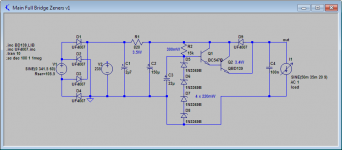
FWIW -- here is the circuit I am contemplating at the moment. I haven't included a choke in the hopes that I don't need one. I think Q1's collector will see a ripple of about 6VAC.

Member
Joined 2009
Paid Member
Bipolar transistors are neither 'voltage gain' or 'current gain' devices - although it can be helpful to consider them as such depending on how you are analyzing your circuit. However, the underlying operation of the device is 'control voltage input = controlled current flow output". You apply a voltage between base and emitter; these are the control inputs (a voltage is always a potential difference between two points). This voltage causes the transistor to vary the current flow between emitter and collector. It's not just bipolar devices, MOSFETs, JFETs, Triodes, Pentodes - all active devices are voltage controlled input and varying current on the output. We use the term 'transconductance' to describe a device where voltage input produces current output.
However, Bipolar transistors have relatively low input impedance at the base, you have to provide current into the base or else the control voltage will sag. The base current is much smaller than the collector current so you need only a small current to drive the device. Because of this, you can think of a current gain, output current divided by input current - but don't let that fool you into thinking it is a current operated device. The output current is controlled but the voltage across base-emitter.
To get a voltage gain you allow the collector current to flow through a resistor. Since V = IR this collector current develops a voltage across the resistor. With the right choice of values this voltage signal at the collector (with respect to the emitter) can be much larger than the voltage signal at the base (with respect to the emitter) and their ratio is the voltage gain.
Last edited:
Bigun … there's nothing "low" or "high" impedance about the base-emitter PN junction, you know. It is a diode. It follows the exponential Ibe = e(Vbe-Vthresh)/kt equation just like any other diode junction, where the Vthresh is a function of the potential well between holes in the P semiconductor, and electrons in the N side.
I is fair to say that because it is a diode, and behaves exactly like a diode, that the current is (near threshold) heavily influence by the voltage of Vbe. Sure. Its like E = IR or I = E/R … you can think of a resistor as "voltage controlled" if you like, or you can think of it as current controlled. Makes exactly NO difference.
This is not the same as the true voltage amplification mechanism of all field-effect devices such as FETs, JFETs, MOSFETs, reverse-biased triodes, tetrodes, pentodes. JFETs and vacuum devices also have forward conduction grid/gate currents which in the case of vacuum devices, does not cause a cascade, but through their exclusive claim to voltage-based-amplification, continues to amplify transconducted current flow. But the electrons in positive-biased grids also jump off, and become a minor part of the cathode-anode current flow. In JFETs, the forward-biased conduction is much closer to what happens in a bipolar transistor, with the injected current resulting in an anomalous controlled current cascade. Quite apart from the voltage-controlled current flow. And quite unpredictable, leading to all nature of distortions in real-world practical circuits.
I could go on, but I doubt it will help: You firmly believe that all amplification devices are voltage controlled; this is just ignoring that the IBE current is itself not anomalously but intentionally amplified through forward-conduction cascading … and that this is an entirely different form of amplification than any field-effect … tube or sand … based device. Entirely.
GoatGuy
All transistors are voltage controlled (strictly charge controlled) devices. So are valves.I could go on, but I doubt it will help: You firmly believe that all amplification devices are voltage controlled;
Base current is a defect, not a feature. JFETs, valves, and BJTs (but not MOSFETS) all have an intrinsic diode between base and emitter. The fact that in a BJT the voltage needed to control the collector current happens to be the same as the voltage which forward-biases the b-e junction is an awkward coincidence, nothing more. Base current is something we have to 'put up with', and we would engineer it out, if we could. Beta (hFE) is not a very useful parameter for transistors, as it varies wildly with temperature and operating point, unlike gm which is highly predictabe..this is just ignoring that the IBE current is itself not anomalously but intentionally amplified through forward-conduction cascading …
Nope, the collector current is gm*Vbe, just as it is for a FET or valve. No difference. This is a very helpful fact since it makes it trivial to understand how all transistors and valves operate! Everything else is just a list of defects peculiar to that particular device.and that this is an entirely different form of amplification than any field-effect … tube or sand … based device. Entirely.
Last edited:
FWIW -- here is the circuit I am contemplating at the moment.
R1 is too high. You are dropping too much voltage.
R2 is too high. You should aim for ~1mA thru the Zeners to maintain proper regulation. With 270K it's less than 0.1mA.
Z1 is overspec'd at 5W. Better use 4 zeners 51V in series, the small 0.5W types will do.
You don't need a 400V Darlington type. The max differential voltage the transistor ever sees is the (max recified line voltage [afterR1] - offload voltage), 100V types should do.
Also, you don't need no big filter cap after the Darlington. Voltage is maintained by the regulator.
I attached a schematic which should work for 115V +/-10% mains variation. Ripple for 50mA quiescent current will be ~3mV. Q2 needs a small heatsink @3.4W max dissipation.
Attachments
- Status
- Not open for further replies.
- Home
- Amplifiers
- Tubes / Valves
- How little B+ ripple do I really need?