Hi, All!
Long-time lurker, seldom-poster here. I've learned plenty from you guys over the years, thanks!
I am building a B+ supply for the preamp below. Its output is pretty hot, around 5Vpp. I am not well-versed in tube amp nor power supply design, but I am okay on the repair side of these things, and have built gainclones and so on in the past.
The amp needs "about" 200VDC B+. I have known folks to run these well over 300VDC, my goal is to hit somewhere above 200V but not too much. To keep cost down, I wanted to start with a Triad Magnetics VPS230-110 transformer, which gives me two 115V secondaries, wired up as a center-tapped 230V. Then a full-wave rectifier (1n4007s), then maybe an LC filter and then some RC filtering to also drop voltage. I figure I'll need to drop about 50-60V, so the Rs in the RC stages would be maybe 1K and 680 ohms.
What I can't figure out is -- how much filtering do I really need? Is a choke stage necessary? (it doubles cost) And a related question, how can I ensure that I don't exceed the current rating of the transformer with the capacitors' inrush draw?
I know that minimal filtering followed by regulation will give me good results. But I am trying to keep this simple enough that I can understand it, built it easily, and expect years of bullet-proof service.
So, to the topic at hand -- how little ripple do I really need with this amp? From an analysis POV, the right hand side of the schematic, connected to output transformer T2, is the interesting one. The left side is just an effect.
I see that the 200V B+ goes to the center tap of the output transformer's primary, whose windings drop 5V per side off it; putting 195V on the plates of V5, a 6SN7 dual triode. The OT is center tapped, with the center tap referencing ground.
So, ripple will ripple equally on both plates, putting them, say, between 185 and 195V if I have 5% ripple. But won't the ripple be cancelled (common-mode) when T2 is connected to a power amp that has a balanced input? Also -- what happens when an unbalanced power amp is used, connected between one side of T2 and the center tap? Does the unbalanced amp hum more in this case, or does the common-mode rejection happen (or half-happen) in the transformer?
If the ripple is cancelled, why do we bother smoothing B+ at all? To keep the tubes working at their optimum voltage? If it is not cancelled..why not?
Thanks,
Wes
Bigger version here: http://theonqgroup.com/pub/bench/BV_-CV_Preamp_Schematic.jpg
Long-time lurker, seldom-poster here. I've learned plenty from you guys over the years, thanks!
I am building a B+ supply for the preamp below. Its output is pretty hot, around 5Vpp. I am not well-versed in tube amp nor power supply design, but I am okay on the repair side of these things, and have built gainclones and so on in the past.
The amp needs "about" 200VDC B+. I have known folks to run these well over 300VDC, my goal is to hit somewhere above 200V but not too much. To keep cost down, I wanted to start with a Triad Magnetics VPS230-110 transformer, which gives me two 115V secondaries, wired up as a center-tapped 230V. Then a full-wave rectifier (1n4007s), then maybe an LC filter and then some RC filtering to also drop voltage. I figure I'll need to drop about 50-60V, so the Rs in the RC stages would be maybe 1K and 680 ohms.
What I can't figure out is -- how much filtering do I really need? Is a choke stage necessary? (it doubles cost) And a related question, how can I ensure that I don't exceed the current rating of the transformer with the capacitors' inrush draw?
I know that minimal filtering followed by regulation will give me good results. But I am trying to keep this simple enough that I can understand it, built it easily, and expect years of bullet-proof service.
So, to the topic at hand -- how little ripple do I really need with this amp? From an analysis POV, the right hand side of the schematic, connected to output transformer T2, is the interesting one. The left side is just an effect.
I see that the 200V B+ goes to the center tap of the output transformer's primary, whose windings drop 5V per side off it; putting 195V on the plates of V5, a 6SN7 dual triode. The OT is center tapped, with the center tap referencing ground.
So, ripple will ripple equally on both plates, putting them, say, between 185 and 195V if I have 5% ripple. But won't the ripple be cancelled (common-mode) when T2 is connected to a power amp that has a balanced input? Also -- what happens when an unbalanced power amp is used, connected between one side of T2 and the center tap? Does the unbalanced amp hum more in this case, or does the common-mode rejection happen (or half-happen) in the transformer?
If the ripple is cancelled, why do we bother smoothing B+ at all? To keep the tubes working at their optimum voltage? If it is not cancelled..why not?
Thanks,
Wes
An externally hosted image should be here but it was not working when we last tested it.
Bigger version here: http://theonqgroup.com/pub/bench/BV_-CV_Preamp_Schematic.jpg
Last edited:
It is not completely canceled, but will be suppressed to a great deal.
How much hum can you live with?
The input stages will be more sensitive than the output stages.
What type of rectifier are you planning on using?
How much hum can you live with?
The input stages will be more sensitive than the output stages.
What type of rectifier are you planning on using?
“I know that minimal filtering followed by regulation will give me good results.”
Yep. You've got it. Your "much learning thru much lurking" instincts are right. Here's something that is rarely offered, but true: if inductors (chokes) cost the same as resistors, then there'd be no resistors in power supplies for their filtering purposes. Inductors have nearly double the low-pass filtering per unit of nominal value, because of course their Z (equivalent of a resistor's R) increases with frequency (or if you prefer, with dV/dt). A resistor is a frequency-agnostic device.
But chokes aren't the same price as resistors, so I see your baseline objection.
I have found in practice that your approach: relatively small C₁L₁ stringer goes a LONG way to sand off the high frequency and easily heard 60 Hz buzz. C₁ around 25 μF to 72 μF, L₁ around 1 H (but can be higher with no downside). After that, a much larger C₂ ≈ 220 μF to 470 μF, then R₂ of 1 - 2 kΩ then another cap C₃ of 220 μF to 470 μF (or even larger, but there is diminishing returns). The resulting Hi V is brilliantly clean and nearly silent.
Your amplifier's schematic will also serve to cancel the residual common-mode power supply ripple. Good CMRR (common mode rejection ratio).
I guess I'm advocating: CLCRC because of L's HF "buzz-buster" capability.
GoatGuy
Hi, TheGimp!
This is a musical instrument preamp, not an audiophile HiFi preamp, so pulling numbers out of the air, I expect I can live with a signal-to-hum ratio of around 80 or 90 dB at my ear.
I have no idea what the SNR of the power amp is ... and am not sure how to factor that into my requirements.
If I understand correctly, 10mV on a 200V supply is equivalent to 86dB SNR.
Which brings up two questions, naturally: how much common hum will be cancelled in the output transformer (especially when used in the unbalanced configuration I described above), AND .... how do I calculate how much capacitance in my RC stages I need to achieve a given goal?
In the past, I have simply thrown capacitors at the problem until the hum went away, but I'm trying to be a bit smarter about design these days. Unfortunately, my analog electronics education is very rudimentary.
I intend to use a full-wave bridge rectifier made with 1000PIV silicon diodes. Probably 1N4001s, I have lots and the current requirements for this preamp are quite low. I understand they draw 15-20mA so I have been trying to do math assuming I need to supply 30mA.
Other questions this brings up: I know how to calculate ripple reduction in dB for LC and RC filters (and I think I could find it for a pi-filter too). But I don't know what the SNR is for the ripple coming out of the power supply, nor to subtract figures in dB. For example, if I have a 50dB SNR and reduce the noise by 50dB, what is the resultant SNR? 3dB?
Wes
You better not use 1N4001, as they are NOT 1000 PIV diodes. They are 50 PIV. Remember that PIV = Peak Inverse Volts. Your 200+ volt supply will have substantially over that, of course.
Buy a bunch of Vishay UF4007. They're not expensive, and when doing tube work, its good to have a bunch in your diode drawer. They are "ultrafast" though, so it puts additional emphasis on using a smallish inductor in the CLCRC configuration.
GoatGuy
(Mouser lists at $3.00 for 10 for the Vishay)
Buy a bunch of Vishay UF4007. They're not expensive, and when doing tube work, its good to have a bunch in your diode drawer. They are "ultrafast" though, so it puts additional emphasis on using a smallish inductor in the CLCRC configuration.
GoatGuy
(Mouser lists at $3.00 for 10 for the Vishay)
Hi, GoatGuy!
Whoops, pretty bad slip-of-the-mind, meant 1N4007 not 1N4001. Thanks for catching that. I think I may have made the same slip when ordering misc stuff last week...I better check my diode drawer.
Good comments w.r.t. step-down chain and especially the choke frequency explanation, thanks. I am surprised that a 1H choke is enough, I normally see 10H or so in circuits I repair. I've been looking at Digikey parts - shipping to Canada is much cheaper than Newark or Mouser. The correct choice seems to be a 10H 50mA unit with DCR=500ohms (Triad Magnetics C-3X), assuming my figures for B+ draw are correct. For the same money I can get 1H 240mA DCR=50ohm. I guess the 1H part gives me more B+ headroom..........Do I need to worry about the choke's current rating for the brief time it takes to charge the capacitor right after it?
When you say, "buzz busting", I guess you're also talking about the high-frequency hash from the diodes, 120Hz harmonics, and so on?
So, CLC-RC is starting to look like the smart choice. <napkin math>$14 + $2 + $14 + $2 + $1 + $2 + $8 = $43</napkin math> delivered to my door, plus a chassis (old PC power supply?), plus parts on hand, plus tax. vs. a pre-built, regulated unit (IHB200-012) from mouser for $90 plus tax delivered to my door. I need a least two of these power supplies.
Interesting options - it really is hard to thoroughly beat pre-built when you include a choke, but still coming in at roughly half the price is not too bad. Being a hobbyist is helpful, because I work for myself for free. 😉
The problem with 1N4007 is buzz. You need to bypass each diode with a snubber (zobel), typically 10nF in series with 47R CC resistor.
The UF4007 is a much better solution.
The UF4007 is a much better solution.
Wes-Ninja250, working "for self" for free … is why we do hobbies such as retro-steampunk DIYaudio. Your napkin math is fine. If you looked about for chokes and transformers, there are OK-enough ones to be had for half that out there. Not so sure when you include shipping. Maybe you're right.
Another way to go is to drop the R in CLCRC, and replace it with a regulator, which for the most part, just is really best thought of as "a resistor with god-like powers". Though some folk don't like 'em much, I do. And they're as near-cheap as dirt, really. About ½ the price of an inductor, or 7–10× the price of a power resistor. Remember god-like powers though are worth something.
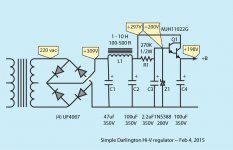
Though nowhere near a perfect regulator, still a high voltage zener, a small 1 μF cap, a couple of resistors and a simple NPN darlington transistor make a pretty darn good regulator. You run it as a bog-standard emitter-follower, with the base powered by the trickle resistor and clamped by the zener and a capacitor in parallel with it. Cheap, simple, effective. Using a darlington changes current gain from Hfe of ≈ 100–200 to over 5,000. Since you're working along the high-voltage chain, the doubled voltage drop of the VBE loss (which will be about 1.5 volts) is of little consequence.
Anyway, here's a picture.
Another way to go is to drop the R in CLCRC, and replace it with a regulator, which for the most part, just is really best thought of as "a resistor with god-like powers". Though some folk don't like 'em much, I do. And they're as near-cheap as dirt, really. About ½ the price of an inductor, or 7–10× the price of a power resistor. Remember god-like powers though are worth something.
Though nowhere near a perfect regulator, still a high voltage zener, a small 1 μF cap, a couple of resistors and a simple NPN darlington transistor make a pretty darn good regulator. You run it as a bog-standard emitter-follower, with the base powered by the trickle resistor and clamped by the zener and a capacitor in parallel with it. Cheap, simple, effective. Using a darlington changes current gain from Hfe of ≈ 100–200 to over 5,000. Since you're working along the high-voltage chain, the doubled voltage drop of the VBE loss (which will be about 1.5 volts) is of little consequence.
Anyway, here's a picture.
Attachments
Though nowhere near a perfect regulator, still a high voltage zener, a small 1 μF cap, a couple of resistors and a simple NPN darlington transistor make a pretty darn good regulator. [...] Anyway, here's a picture.
Some notes:
Zeners have huge tolerances, you can easily end up with a 190V regulator. Or 210V.
High voltage Zeners also have a large temperature coefficient. Voltage is nowhere stable, but varies on hot and cold days. Or with amp heating up.
Both effects can be alleviated by using a string of several lower voltage zeners.
But once you're there, why not go for a real regulator?
Also, if you need to drop ~100V from rectifier to B+, you should make C1 much smaller than 47uF. Saves power and less hum in the tranny.
I like your handle: “goldenbeer”. Seeing as you have the Colors of Deutschland, we would probably agree upon what to drink.
In reading your comment, and thinking on mine, it is pretty clear that what you wish to regulate, and what I normally design to regulate are two different animals. I spec a regulator as a transparent, cheap, active component that will squash ripple like a giant choke. This is audio, not medical instrumentation, and the precise value for tha job doesn't really much matter.
Reviewing a few dozen different types of Zener Diodes, I do agree with you, that to create a good little regulator that achieves a particular voltage with some precision requires a few Zeners in a string. They're pretty cheap, the 2% parts, 1.⁵W each, with 0.075% per degree temperature coefficients. Putting that in perspective, at $0.10 each, one could get 4 or 5 of the 51 volt, 2% Vishay BZX55B51-TR parts, and put 'em in series. They're only ½ watt each, but 4 of them makes 2 watts.
2% strung precision becomes about 1.3%, so 200 V ± 2.6 V. clearly pretty darn good. The 0.075% thermal coefficient results in a 30 × 0.075 × 1/100 × 200 = 4.5 V voltage swing from cold to hot. Your house or studio temperature then just adds to that. Few studios or pleasant places are more than ±10 C from 20 C. So, ± 1.⁵V from 4.5 over the course different nominal environmental conditions.
LASTLY (and this is where perhaps we: you & I - differ the most), any decent tube-based design is cast into numbers specifically to operate over a pretty substantial variance of non-regulated line voltage, environmental conditions, component variance and tube-conduction (ageing) variance. I mean … "they're tubes, dude!". That gain varies all over the place as they age.
This exposes the folly of falsely specifying precise values and precision "everything" like some never-to-be-achieved engineering fantasy. If I was given a box of ±20% everything (caps, resistors, tubes, power…) I would simply design almost all sections to be relatively immune to the effects, and then hand-select the components that are in those positions in the design where precision does make a difference.
The only time precision-everywhere makes much of a difference is in production, where repeatability exponentially pays off in reduced "per chassis fiddling". That's why we take the time with a few thousand tubes (in production) to match them. That's why we spec precision stuff - just so as to avoid trimming. Can't really specify precision capacitors, but there's little like between precision and quality in those bad dogs. Except for RIAA compensation circuits, rarely does having a larger than spec capacitor have a negative consequence. And so it goes. Same for chokes. Larger is better, except when we call them "inductors" and use them in phase or frequency active sections.
GoatGuy
In power amps I compare all ripple sources to a 1watt output signal at the the specific point in the circuit and aim for the ripple to be at least -85db from the signal. In your case I´d aim for -85db referred to a 1Vpp output. Regulation is the best way to go and in most cases even a crappy regulation can exceed the -85db regulation I aim for.
Wow! Great feedback in this thread. That's why I love this forum even though I seldom post, the expertise is fantastic. Feel free to ask me about certain models of Hammond organs or Ninja 250 motorcycles if you'd like me to contribute back 😀
Vishay UF4007 - I wasn't aware of this part. This is excellent, I will certainly purchase some. I remember now, my gain clone had zobel networks. It was an LM 3886 design from here, I think Brian somebody or other...several years ago. Great sounding amp, I used a monster toroidal transformer that gave me 35V rails and as much current as the LM3886 could sink if I remember correctly.
Goatguy - thanks *very* much for the circuit showing the Darlington pair with the zener used as a regulator. I did not know it would be that easy. I am going to have to do some thinking as to why/how that works. I had originally eschewed Zeners in this design because I understood that they could be noisy? Is that what C3 is there to take care of?
Now, here's a question, with that regulator, is the PI filter necessary, or can it be replaced with an RC filter? How good is the regulation? (Note that my definition of regulation is "how flat is the DC" not "what voltage is the DC").
Can Z1 be replaced trivially with an LR8, and would there be a point w.r.t. noise? I originally looked at one of those but couldn't get my head around how to get more than 20mA out of one. I just have to get 200V to the base of Q1?
What sources are you guys using with chokes and transformers cheaper than Digikey? Those two were ~$14ea CAD, that's about $11 USD. The Canadian dollar has taken a beating lately, as it's tied to oil prices. I pay $8 flat-rate shipping from Digikey (free over $200), Mouser and Newark start at $20 and I think cost more for heavy items. Parts-Express shipping starts at about $40. I stopped by Active Surplus in Toronto yesterday, they didn't have anything really suitable in stock. I thought about building a voltage ladder from a 24VAC transformer I have lying around, but realized I would probably spend more in capacitors than I saved on the transformer.
Wes
Last edited:
marcelop, where did your suggestion to reference to 1Vpp come from? Is it for a typical preamp? This one is not typical, max output is around 5Vpp, maybe a bit more. Or was 1Vpp chosen just to make the math easy?
1Vpp can drive a normal power amp to full output, if you use 5vpp as the -85db ripple reference you´d get 280uVpp hum, which referred to the 1Vpp (which is what I assume a normal power amp requires) equates to -71db which can most likely be heard from the listening spot. All the same 1Vpp was a vague geusstimate.
Yes, Z1 can be replaced with LR8 or any other high-voltage regulator. The purpose then of Q1 is to simply amplify (in a trivial sense) the output of LR8 in the emitter-follower sense. As they say in the business, "whatever floats your boat". I'm old fashioned enough that I like zeners - because I understand them - and therefore I know how to make them do what I want. The chipmakers make superior things called "regulators", which are really quite good at what they do, too. Boats, and floats.
GoatGuy
GoatGuy
These 1A diodes sell for about $.35 each at Mouser. If you "look around" their website you will find that 3A equivalents sell for about the same price.Vishay UF4007 - I wasn't aware of this part. This is excellent, I will certainly purchase some.
Wes
Go for the UF4006. PIV is still high enough and the Vishays sell for half the price of the UF4007.
I understand that zeners allow for a crude kind of regulator, it's just that I do not find their performance too compelling.
Note that temperature in the chassis may vary a lot more that just +/-10°C, depending on where you place the zener. The pass transistor (and probably other stuff) will burn off some heat, and 50~70°C are not out of reach.
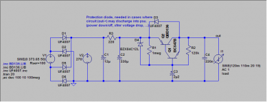
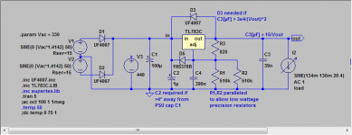
With all the tolerances and variability, the zener regulator is not much better than your mains line variance. In which case you may forego any regulation and use a simple cap multiplier, see 1st attachment. You can adjust the offload voltage by varying C1 and R3. Also wastes less power and no heat sink required for the pass transistor in most cases.
Otoh, a real regulator is also not much more difficult to employ, as long as currents are reasonable so that you don't need a seperate pass element. See 2nd attachment.
Note that temperature in the chassis may vary a lot more that just +/-10°C, depending on where you place the zener. The pass transistor (and probably other stuff) will burn off some heat, and 50~70°C are not out of reach.
With all the tolerances and variability, the zener regulator is not much better than your mains line variance. In which case you may forego any regulation and use a simple cap multiplier, see 1st attachment. You can adjust the offload voltage by varying C1 and R3. Also wastes less power and no heat sink required for the pass transistor in most cases.
Otoh, a real regulator is also not much more difficult to employ, as long as currents are reasonable so that you don't need a seperate pass element. See 2nd attachment.
Attachments
I think this is a little unfair on the poor Zeners! The Zener voltage will typically increase by 2 to 3% for a 30°C rise (e.g from 20°C to 50°C, which is realistic for the inside of a chassis). This is significantly better than mains voltage variation; valve circuits almost never need anything more accurate, and the temperature inside the chassis is unlikely to vary much after the initial warm-up period anyway.I understand that zeners allow for a crude kind of regulator, it's just that I do not find their performance too compelling.
Note that temperature in the chassis may vary a lot more that just +/-10°C, depending on where you place the zener.
With all the tolerances and variability, the zener regulator is not much better than your mains line variance.

You are all correct about the Zeners. It's just that why would you go for all the hassle, when a TL783 + heatsink is about 2 bucks when bought in small quantity, and the remainder of parts for a full regulator is all pennies? You can then even save on big filter caps, since the regulator smoothes it all out. The most expensive part of the whole thing will be the (big) HV reservoir cap.
Well, I can think of three reasons not to use a small regulator
In any case, use what floats your boat..
Well, I can think of three reasons not to use a small regulator
- your currents are too high, so you need an extra pass element, which complicates matters
- you do not like heatsinks or to burn off excessive power
- you do not like silicon error amplifiers as part of your audio signal loop (as would be in a typical class A amp, and most other topologies as well to a certain extend)
In any case, use what floats your boat..
- Status
- Not open for further replies.
- Home
- Amplifiers
- Tubes / Valves
- How little B+ ripple do I really need?