So, whats the prob with Differential White Cathode Follower of
Post #4??? Trick two triodes to do three jobs simultaneously,
and suddenly nobody can follow how it works anymore???
1) Voltage regulator 2) Inverter 3) White Cathode Follower...
From a single twin triode no less.. On as little as 80V B+.
Perhaps I havn't made clear how common mode noise rejection
and power supply ripple rejection far betters over Lampizator?
Or how it can slew cleanly and symmetrically into much lower
impedance loads. 4K7 on up, no problem at all....
Especially if the twisted pair from from DAC to amp must be long
and travel through interference. Or they have different supplies
with different noise. CMRR and PSRR would be very nice to have
at the far end to unscramble all that mess...
Not significantly more parts nor complexity than Lampizator.
Can't figure why its gotten no traction whatsoever. Is not one
of you bold enough to bite the bullet and try something new?
Granted, both I and my designs ARE often completely insane...
But in light of the posted sim results: This particular insanity
seems uncharacteristically plausible, coming from me....
Last edited:
A real quick question. I am going to tube my Denon 2900, and the DAC has Iouts normal, and inverted. Do I use just one set? Does the tube invert the signal?
Thanks much.
Ben
Thanks much.
Ben
You can use topology like SRPP which will invert your signal.
More info:
http://www.freewebs.com/valvewizard1/srpp.html
More info:
http://www.freewebs.com/valvewizard1/srpp.html
Thanks much for the link. I am still confused about which set of Iouts to use, or use both and sum them. There are 2 per channel with one being inverted.
Ben
Ben
A real quick question. I am going to tube my Denon 2900, and the DAC has Iouts normal, and inverted. Do I use just one set? Does the tube invert the signal?
Thanks much.
Ben
You may want to use two SRPP circuits, but with both bottom triode cathodes connected together. This will act like a differential pair, and as one Iout increases output current, and the other Iout decreases current into their respective Rg1 resistors, the resulting voltages should make one triode of the pair increase cathode current, and the other should decrease current by the same amount. The cathode resistor should see the same current at all times, as one triode takes more, the other takes less. The rest of the SRPP's stay conventional (the top triodes). Thus giving you differential audio outputs, so you could use those fancy 3 pin mic connectors for output jacks, like those used in radio stations. This does get to be a lot of tubes (4 twin triodes) though...
Is it possible to create a PCB layout and offer them for a group buy?
I am ready with the design of the Lampizator PCB with addition of my Heater-Switch circuit.
Unfortunatlely i got no response from Lukasz about the PCB.
Anyway, with great respect for his discovery of this stage as a great sounding upgrade to standard I/V output stages,
i don´t think he had a problem with it because it is a simple and old SRPP design.
Best regards,
Oliver
The SRPP is push pull and over kill for a DAC if you have an amp with a good (50khoms) input impedance.
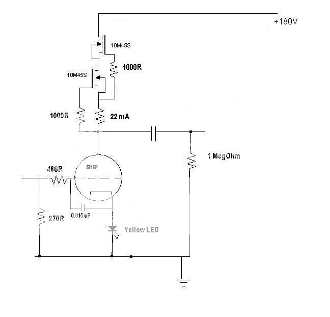
I have tried this SET stage and it sounds much better because it doesn't have the load unbalancing the push-pull like the lampizator:
I have tried this SET stage and it sounds much better because it doesn't have the load unbalancing the push-pull like the lampizator:
Discovery?I am ready with the design of the Lampizator PCB with addition of my Heater-Switch circuit.
Unfortunatlely i got no response from Lukasz about the PCB.
Anyway, with great respect for his discovery of this stage as a great sounding upgrade to standard I/V output stages,
i don´t think he had a problem with it because it is a simple and old SRPP design.
Best regards,
Oliver
To my eyes it looks very similar to Audio Note's output stage, only other type tube...
Attachments
The SRPP is push pull and over kill for a DAC if you have an amp with a good (50khoms) input impedance.
I have tried this SET stage and it sounds much better because it doesn't have the load unbalancing the push-pull like the lampizator:
Hi!
I show use CCs by 10M45 for 6h6 or 6h30, the sound is not good!
in the cricuit you tube 6h30 is better!
Thank
Here my shanling CD-T100se with SRPP 6n6p.
I removed all the opamps and the 6n3 tube outputstage. Now i just use i/v resistor and SRPP tubebuffer with 6n6p with just one ( output ) capacitor.
I like this setup more, it has more detail and the overall sound picture is more complete then the origenal build. I did together with several other persons abx listen testing and every body heard the difference. I do not say with is best because this is a matter of personal taste.
Some experience i like to share:
It is important to match the output impedance with the following stage. Then only you got minimal distortion and maximal linearity. I use this excel sheet to calculate the value of the resistors.
http://www.ict-net.net/tube.xls
It is also important that the following stage has a constant impedance.
About noise and hum, if your loudspeakers are not to sensitive( < 95db ) then you can use the 6n6p as srpp with a simple powersupply in your audio equipment. Hum and noise will not noticeble. Still there are schematics who will measure better. But will they sound better?
In my case not.
An externally hosted image should be here but it was not working when we last tested it.
Last edited:
About noise and hum, if your loudspeakers are not to sensitive( < 95db ) then you can use the 6n6p as srpp with a simple powersupply in your audio equipment. Hum and noise will not noticeble.
Also with my 107dB Horns there is no hum or noise (6N2P). Absolute silence 🙄
Hello, I am using a Marantz CD63 KISS and I was thinking to try this mod.But as I remember it has a muting circuit somewhere at the audio output that failed once (probably a cap discharge through the interconnects destroyed a transistor) and then a poping sound was audible between tracks. My concern is if this bypass of opamp will include this muting circuit and cause any unwanted sounds. I have not seen in the schematics if it is at the opamp output, has any member an experience regarding this?
Pointy, in everthing with a dac you can build a lampizator. Just look for the L + R our pins on the DAC.
I did something like that with a pinnacle soundbridge M500.
http://www.diyaudio.com/forums/digital-source/123710-wifi-internetradio-tubeoutput-stage.html
Ronny
I did something like that with a pinnacle soundbridge M500.
http://www.diyaudio.com/forums/digital-source/123710-wifi-internetradio-tubeoutput-stage.html
Ronny
nice............with a DVD + hard-drive you would have CD player + mp3 hard-drive, plus wifi up loading and last but not least a remote control. have you an schemo of a line stage that may be used. very very please...........
pointy, first you must do some work yourself. Witch dac has your player?You must know this first if you have a current of voltage output dac. So tell me.
Ronny
Ronny
hi everybody,
will be possible the tube modding also with the TDA1540?
You can se here:
http://www.diyaudio.com/forums/group-buys/155960-dac-end-andrea-ciuffoli-group-buys-12.html
- Status
- Not open for further replies.
- Home
- Source & Line
- Digital Source
- How Lampizator CD tube player sound?