Hi,
I've been trying to study a number of power amp designs lately. I'm attracted by SE designs mainly because of the THD profile where d2 dominates d3. But then, there are the obvious drawbacks. Now, there are some PP designs out there that feature a THD profile where this is not the case. (For example the PP1-C, PP2-C)
What is being done differently in those design? Is it just the absence of NFB?
I mustsay that I am not completly clear on why, in general, PP tends to exhibit this particular profile. Again NFB is probably a contributor but what are the other factors at play?
Cheers,
Lars
You mean harmonics? H2 and H3?
Even - asymmetrical distortion such as valve load line (a function if you will) that distorts the signal unequally.
Odd - symmetrical distortion (such as symmetrical clipping or zero transition problems)
Things like CCS help reduce distortions by flattening the load line - therefore a signal can remain in the more linear areas. You can create a design that doesn't overload the stage but uses multiple stages to keep in the linear area.
Zero transition symmetrical distortion by AB or B class increases odd harmonics. It's also possible to run push pull without zero transition in class A. Less efficient, less output but you don't have a zero transition and so there's a lot less odd harmonics.
Feedback simply compares the input, the output which then identifies the harmonics and therefore allows you to reduce the harmonics.
Lars,
A PP O/P stage cancels even order distortion products that are generated internally. Careful selection of the small signal circuitry can allow the net distortion spectrum to be an ear pleasing "waterfall" of H2>H3>H4 ...
A PP O/P stage cancels even order distortion products that are generated internally. Careful selection of the small signal circuitry can allow the net distortion spectrum to be an ear pleasing "waterfall" of H2>H3>H4 ...
Careful selection of the small signal circuitry can allow the net distortion spectrum to be an ear pleasing "waterfall" of H2>H3>H4
Is small signal circutry here referring to the driver stage and phase splitter?
Do you have few pointers in terms of properties that thes crcuits need to exhibit in order to get to this "ear-pleasing" THD profile?
Thanks!
Is small signal circutry here referring to the driver stage and phase splitter?
Do you have few pointers in terms of properties that thes crcuits need to exhibit in order to get to this "ear-pleasing" THD profile?
Thanks!
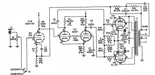
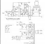
The small signal circuitry is everything prior to the power O/P stage. There are 3 small signal stages in Williamson topology: voltage amplifier, phase splitter, and differential amplifier.
The distortion of spectrum of a resistively loaded 12AT7/ECC81 section voltage amplifier is skewed towards the 2nd harmonic. It is possible to exploit that fact in Mullard style circuitry with say a μ 22/low RP ECC99 as the phase splitter and Russian 5881 equivalent 6Π3C-E (6p3s-e) "finals". The idea is a rehash of the EICO HF89.
Force symmetry in the LTP phase splitter by using a 10M45S constant current sink (CCS) as the "tail" load.
Full pentode mode "finals" are fine, if you regulate g2 B+ at a fraction of anode B+.
Attachments
I'm no expert but from the experimentation I've done using low gain valves like the ECC82/6SN7 and using a CCS and negative rail for the PS as outlined in post #5 is the way to go. Low value ish anode resistors IE 47k result in more 2H as does a low value grid leak resistor in the following stage, it tilts the AC loadline,makes it steeper = more 2H. I design my amps not to have very low distortion, my recent AB2 amps have 4% THD at full power but sound sweet, to my ears at least.
Your OPT has a lot to do with it too, you want your PP OP stage to stay in Class A as long as poss. There's a sweet spot I find, where with the volume is set just right, a bit above normal listening level but not at party level sounds best. This means not too much NFB, biased a bit hotter than normal and with good AC balance.
Regarding good AC balance, I make a lot of my stages adjustable,so adjustable CCS, adjustable bias & bias balance on fixed bias amps and regulated screen grid supply. This allows you to experiment a bit, have a play with DC/AC conditions.
Andy.
Vacuum Tube SPICE Models
Vacuum Tube SPICE Models
I scanned through nine tubes found 2nd harmonics has a lot to do with the tube characteristic themselves not the SE output itself. The more linear the tubes are the less 2nd harmonics they have. For less linear tubes, not all is lost as the pre-distortion correction can be designed into driver stage, if you look at their drivers output or grid of output you can see how non-linear (read much more 2nd harmonics) compared with output using a driver with very little distortion.
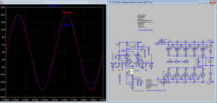
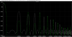
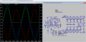
In PP amp, 2nd harmonic (and even harmonics) level can be easily raised to the same level as SE amp as attached, using differential voltage feedback to LTP driver stage making NFB optional.
Attachments
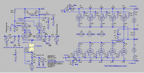
The way I did it was by having a LTP input, and through a voltage divider, create a difference between both bias points of the output stage, that is direct coupled.
There is a sliding ramp, where you can see the second harmonic appear in plus or minus phaase, as you ‘dial’ in the change of bias.
I did that on the output stage, because it fitted my design.
Others have done this trick on the input (notably, the famous designer Héphaistos).
There is a sliding ramp, where you can see the second harmonic appear in plus or minus phaase, as you ‘dial’ in the change of bias.
I did that on the output stage, because it fitted my design.
Others have done this trick on the input (notably, the famous designer Héphaistos).
Despite my best efforts, all of my push-pull amps have been 2nd harmonic dominant, just from gain mismatch between the two sides of the channel.
Tubes pairs will always have some mismatch in gain and that creates even harmonics.
I even tried introducing adjustable mismatch in the phase splitter and I couldn't get 2nd to go below 3rd.
Tubes pairs will always have some mismatch in gain and that creates even harmonics.
I even tried introducing adjustable mismatch in the phase splitter and I couldn't get 2nd to go below 3rd.
If the amp is PP pentodes the odd order harmonics 3rd, 5th, 7th & so on can be driven down by using a loadline of lower impedance than that given in the tube data sheets. For example, if the data asks for 10K p-p, use an OPT that will reflect 8K p-p to the power stage.
This also helps the problem associated with the complex load of a loudspeaker. For much of program spectrum the load impedance can be considerably higher than what the speaker impedance spec is. For example, a typical 8R speaker will measure 6.5R on an ohmmeter. But the real load depends on the cabinet & any cross over network(s) as well.🙂
For triodes a higher p-p load impedance will reduce D%.
Last edited:
Regarding the differential pair cascode FB, I played about this and got nowhere, mind you it could be my stage didn't have enough gain and I didn't really know what I was doing at the time. The problem I encountered when I tried this was the NFB didn't do anything, I tried altering the phase of the FB, amplitude etc, gave up in the end.
Andy.
Can you clarify? How do you mean both bias points. A fixed bias OP stage has one bias point.....create a difference between both bias points of the output stage...
Andy.
If the push and the pull output tubes draw a different amount of current then they must have different bias points.
You can use a bias servo to measure and alter this by a controlled amount.
Normally you'd use a bias servo to force a second tube to match the current that is put through a sampled output tube, but if you deliberately mismatch the small fixed resistors it measures over, then that has to reflect in deliberately mismatched bias points.
Since the opamp doing the comparison is a high impedance device and draws negligible current (a few uA at most), it'll have neglibible effect on the sound if the time constant it acts over is long enough.
kind regards
Marek
Sim files for sharing, for those interested can compare FFT using NFB, Unbalanced plate resistor and differential feedback in LTP.
Attachments
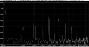
I think one thing we miss in simulation is mismatch between devices in pp circuits. No two tubes are ever exactly alike but models are perfectly matched. I count on more 2H than I see in simulation. Would a typical mismatch be enough for 2H to dominate in a 0 nfb circuit? I suspect not unless you were dealing with very low levels of 3H
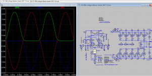
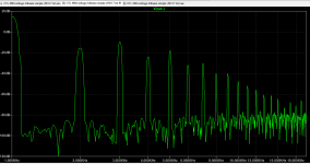
Yes, I can sim mismatched tube, the Mu of lower bank is increased by 14% compared with normal Mu under same setting. The bias is reduced so you see crossover distortion. 2nd harmonic is increased as well as 3rd and that is why you can not get 2nd harmonic greater the 3rd which is generated by crossover distortion, different story with matched tube as sim before.
Attachments
Last edited:
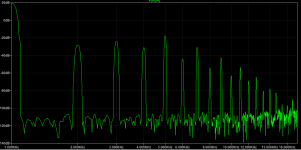
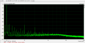
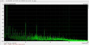
These are real measurements of my push-pull Unity-Coupled amp at 1W and 10W.
I see no reason that you couldn't purposely introduce some mismatch in the phase splitter of an amp to introduce some even-harmonic distortion if you wanted it. I was trying to minimize the distortion in my amp, so I introduced an adjustment to purposely counteract the gain mismatch. The attached measurements represent the lowest level of even harmonics I was able to achieve.
I see no reason that you couldn't purposely introduce some mismatch in the phase splitter of an amp to introduce some even-harmonic distortion if you wanted it. I was trying to minimize the distortion in my amp, so I introduced an adjustment to purposely counteract the gain mismatch. The attached measurements represent the lowest level of even harmonics I was able to achieve.
Attachments
- Home
- Amplifiers
- Tubes / Valves
- How is d3 dominanc avoided in some PP designs?