How I adapted a speaker protection board to my amplifier power supply.
I must admit that I'm a newbie to DIY audio. I know the basics of electronics, but I'm not able to make a design myself. I found a lot of helpful posts in the forums of DIYaudio, so I thought maybe I could do something in return. That's why I wrote this post.
Inspired by a lot of articles I read about the "gainclone", I decided to build a set of 2 LM3886 mono power amplifiers. In these articles I also read about the importance of a speaker protection board. As I bought the LM3886 kits from Chinese resellers, I also looked there for a speaker protection board that I could use.
I found several, but all of them had a limited power supply range, and neither of them was in the range that I would need, having a 20 VAC transformer, and 29 VDC at the output of the power supply. These kits all used the NEC uPC1237 Protector IC.
After reading the datasheet I found that the initial power supply range for this IC is 25 - 60 VDC.
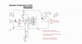
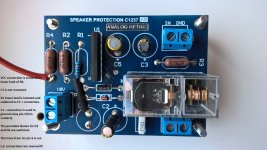
So, I found a nice looking set of mono speaker protection kits at AnalogMetric. The good thing is that the kit is very well documented at their site, with a schematic, BOM and user manual.
I compared the schematic with the one from the uPC1237 datasheet, and thought that it would be not too difficult to modify it to my needs.
According to the kit documents, it can be used with Supply voltage 35-48V AC or 15-24V DC. So what did they do? AC as well as DC power can be applied to the power input.
If AC is used, the smoothing capacitor C1 will smooth out the ripple after the half-wave rectifier diode and make it a usable VCC, that also supplies power to the relay.
If DC is used, the rectifier and capacitor are still there, but the function is not used.
This input voltage also is provided to pin 4 of the IC. According to the datasheet pin 4 is used to detect the presence of AC power. When AC power goes off, the IC will trigger the relay to open.
If a DC PSU is connected to pin 4, it will take a long time before the PSU capacitors have lost their power, and the relay wouldn't open immediately.
So, I decided to separate VCC from AC, replace R1 and R4 for values that are fit for the applied power and add R6 in the connection to the relay coil to make sure only 24 VDC is supplied to the relay.
Now I apply 20 VAC to the AC input and 29 VDC to the DC input. As you can see in this post and in the pictures it is easy to calculate the value for R1, R4 and R6.
I also read an interesting article at halfgaar.net about Speaker DC protection with relays. They found that when an emergency occurs to the amplifier the relay contacts often melt together i.s.o. breaking the connection to the speaker. By connecting the N.C. contact to ground, the relay lasts longer. This implies that the speaker needs to be connected to the central contact, and the amplifier to the N.O. contact.
So this is what I did:
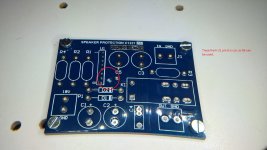
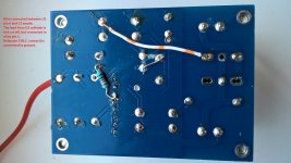
- Input and output connections to speaker are reversed. N.C. contact (3) is connected to GROUND!!!
I read about it in this article. Connection is made at the back side of the PCB.
Be aware that if you don't reverse input and output, the amplifier output is shorted to GROUND!!!
- VCC is cut loose from AC in. The DC in connection is made at the lower lead of R4. At the back side of the PCB the trace between D1 cathode and D2 cathode, and the trace between D1 cathode and relay pin 1, are cut. The lead from D2 cathode is not cut off, but connected to the relay pin 1 (back side of PCB)
- R6 is inserted between U1 pin 6 and the relay pin 8/D2 anode, at the back side of the PCB. R6 can be adapted to VCC. R6 (ohm) = (VCC - V relay) / I relay.
The trace at PCB front side from U1 pin 6 needs to be cut.
- C1 (smoothing capacitor) is no longer needed, because VCC is separated from AC in.
- VCC current is no longer running from P1 pin 2 so I switched the diodes. The larger diode is now used as flyback diode (D2), and the smaller one in the AC detection line (D1).
- R1 lower lead is isolated and soldered to the C1 + connection.
- I did not use the speaker GND connections of the board, but connected speaker ground and amplifier ground to star ground in the enclosure. The board itself is also grounded to star ground.
I must admit that I'm a newbie to DIY audio. I know the basics of electronics, but I'm not able to make a design myself. I found a lot of helpful posts in the forums of DIYaudio, so I thought maybe I could do something in return. That's why I wrote this post.
Inspired by a lot of articles I read about the "gainclone", I decided to build a set of 2 LM3886 mono power amplifiers. In these articles I also read about the importance of a speaker protection board. As I bought the LM3886 kits from Chinese resellers, I also looked there for a speaker protection board that I could use.
I found several, but all of them had a limited power supply range, and neither of them was in the range that I would need, having a 20 VAC transformer, and 29 VDC at the output of the power supply. These kits all used the NEC uPC1237 Protector IC.
After reading the datasheet I found that the initial power supply range for this IC is 25 - 60 VDC.
So, I found a nice looking set of mono speaker protection kits at AnalogMetric. The good thing is that the kit is very well documented at their site, with a schematic, BOM and user manual.
I compared the schematic with the one from the uPC1237 datasheet, and thought that it would be not too difficult to modify it to my needs.
According to the kit documents, it can be used with Supply voltage 35-48V AC or 15-24V DC. So what did they do? AC as well as DC power can be applied to the power input.
If AC is used, the smoothing capacitor C1 will smooth out the ripple after the half-wave rectifier diode and make it a usable VCC, that also supplies power to the relay.
If DC is used, the rectifier and capacitor are still there, but the function is not used.
This input voltage also is provided to pin 4 of the IC. According to the datasheet pin 4 is used to detect the presence of AC power. When AC power goes off, the IC will trigger the relay to open.
If a DC PSU is connected to pin 4, it will take a long time before the PSU capacitors have lost their power, and the relay wouldn't open immediately.
So, I decided to separate VCC from AC, replace R1 and R4 for values that are fit for the applied power and add R6 in the connection to the relay coil to make sure only 24 VDC is supplied to the relay.
Now I apply 20 VAC to the AC input and 29 VDC to the DC input. As you can see in this post and in the pictures it is easy to calculate the value for R1, R4 and R6.
I also read an interesting article at halfgaar.net about Speaker DC protection with relays. They found that when an emergency occurs to the amplifier the relay contacts often melt together i.s.o. breaking the connection to the speaker. By connecting the N.C. contact to ground, the relay lasts longer. This implies that the speaker needs to be connected to the central contact, and the amplifier to the N.O. contact.
So this is what I did:
- Input and output connections to speaker are reversed. N.C. contact (3) is connected to GROUND!!!
I read about it in this article. Connection is made at the back side of the PCB.
Be aware that if you don't reverse input and output, the amplifier output is shorted to GROUND!!!
- VCC is cut loose from AC in. The DC in connection is made at the lower lead of R4. At the back side of the PCB the trace between D1 cathode and D2 cathode, and the trace between D1 cathode and relay pin 1, are cut. The lead from D2 cathode is not cut off, but connected to the relay pin 1 (back side of PCB)
- R6 is inserted between U1 pin 6 and the relay pin 8/D2 anode, at the back side of the PCB. R6 can be adapted to VCC. R6 (ohm) = (VCC - V relay) / I relay.
The trace at PCB front side from U1 pin 6 needs to be cut.
- C1 (smoothing capacitor) is no longer needed, because VCC is separated from AC in.
- VCC current is no longer running from P1 pin 2 so I switched the diodes. The larger diode is now used as flyback diode (D2), and the smaller one in the AC detection line (D1).
- R1 lower lead is isolated and soldered to the C1 + connection.
- I did not use the speaker GND connections of the board, but connected speaker ground and amplifier ground to star ground in the enclosure. The board itself is also grounded to star ground.
Attachments
-
 schematic AM.JPG41.3 KB · Views: 727
 -
 schematic modified.JPG83.6 KB · Views: 695
 -
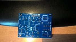 PCB front side original.jpg545.3 KB · Views: 673
 -
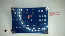
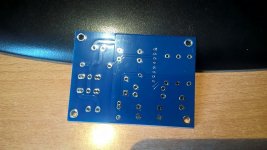 PCB back side original.jpg561.1 KB · Views: 608
 -
 PCB modifications at front side.jpg592.9 KB · Views: 567
 -
 PCB modifications at back side.jpg593.9 KB · Views: 200
 -
 Completed board.jpg627.7 KB · Views: 280
 -
 Components mounted at back side.jpg520.4 KB · Views: 275
 -
 Speaker protection mounted.jpg504.7 KB · Views: 397
Connecting unused pin of relay to ground will short output of amp.
Its the arcing that kills the relay. I always put a 100nf across the contacts to save the relay. This reduces the arcing.
Its the arcing that kills the relay. I always put a 100nf across the contacts to save the relay. This reduces the arcing.
friends, i would like to adapt my upc1237 on switching power supply ....
but there are many problems with this power supply.
it is very complicated to get constant voltage to pin 4.
if to be low load, power supply to pump little, and to supply little voltage to pin4,
while if to be very charged, it will pump a lot, and provide a lot of voltage ....
in short it is very difficult to supply the right voltage with switching Power supply ...
do you have any idea?
I almost thought I was taking the signal from a 230v Ac switch.
I thought I would put a 230v ac, diode, and 166k resistor.
the constraint is that the 0 of the circuit must be common with 230v grounding ....
I have tried it and it works.
I was wondering if it can give problems to connect the circuit ground with the 230v ground
pietroruta
The LM3886 have built-in protections. I believe You don't need a separate circuit.
Normally the voltage that feds the Upc comes from the Amp supply rail.
Why You don't just wind a few turns on the trafo to get the 18V Voltage and then rectify / regulate for steady 18V ?
Are You refering to safety ground (green / Yellow) or are You confusing Neutral (Blue) with ground ?
What happens if You reverse the plug on the second case ? Your supposed ground is now live and Your expensive speakers will BOOM !!
The LM3886 have built-in protections. I believe You don't need a separate circuit.
Normally the voltage that feds the Upc comes from the Amp supply rail.
Why You don't just wind a few turns on the trafo to get the 18V Voltage and then rectify / regulate for steady 18V ?
I was wondering if it can give problems to connect the circuit ground with the 230v ground
Are You refering to safety ground (green / Yellow) or are You confusing Neutral (Blue) with ground ?
What happens if You reverse the plug on the second case ? Your supposed ground is now live and Your expensive speakers will BOOM !!
I am referring to the yellow-green earth. I also have a free winding on the transform. but getting constant AC current is very difficult. when not being lightly charged in AC be around 15 v, when I turn up the volume they start to increase, until I get to about 30v AC ..... that's why I thought to take control of the AC from the 230v power line. it has an immediate response and a good tolerance
Whatever it is that you're trying to do, if it involves mains AC the answer is probably no.
Yellow-green? PE? You don't want no stinkin' PE connection anywhere in your actual amplifier circuit. Not in consumer audio. If you've got unbalanced amplifier inputs only (presumably), chances are you want a Class II appliance, all floating (preferably with a shield winding in the power transformer). This is part of why SMPS must be applied with great caution and you can't use just any random one. It must have the mains filter PE connection separated from output ground, so that a Y2 capacitor of typically a few nF can be used to connect the two if not already present within the supply. PE must also remain confined to the mains filter itself, with amplifier case being on secondary-side ground.
(If you cannot find a mains transformer with shield winding but need one bigger than 50 VA or so, you can use the same approach to PE involvement as for a SMPS, i.e. a few nF of Y2 capacitor from secondary-side ground to PE and nothing else. This will mostly drain the mains leakage current from the several hundred pF worth of transformer coupling capacitance so the amplifier will not hum on its own with the input open, but is still high enough in impedance to not cause you any grief with ground loops.)
In order to supply pin 4, I would suggest adding about the smallest mains transformer you can find in parallel to the existing supply - like 3 VA (I've seen ones down to 1 VA and below, absolutely tiny things), voltage not particularly relevant since you can change the series resistor in between (R1) depending on needs as per datasheet fig. 5, so 9 V~ would do just fine.
This could also double as the supply for a soft power circuit if needed, even a micro with remote IR receiver and all.
In any case you need some sort of galvanic isolation device - a solution involving an optocoupler may also be feasible. But if the SMPS does not provide power-on detection of this kind already, I would just go with the extra transformer.
I noticed something in your original mod:
Reversing speaker input and output seems fair enough - however, you forgot to reroute output detection resistor R3 to the other side of the relay. This would keep the circuit from operating properly in case of a fault, causing it to cycle like a relaxation oscillator.
Last edited:
sorry ..... the experiment, to draw with the characters did not go well.
the primary and secondary of the smps are completely isolated. I will try to find another solution. or add a turn to transformer. or insert a voltage and current regulator at the transformer main output. although I think it's not a good solution, as there are 20000uf of filter per channel at the smps output. the descent will therefore be very slow
the primary and secondary of the smps are completely isolated. I will try to find another solution. or add a turn to transformer. or insert a voltage and current regulator at the transformer main output. although I think it's not a good solution, as there are 20000uf of filter per channel at the smps output. the descent will therefore be very slow
Last edited:
dear friends, today i spent a whole day doing smps tests .... there are only 3 solutions. the first is to insert mechanical relay to isolate pin 4 when ac input is off. the second with additional transformer. the third is with a detection system between 230v AC input and with yellow-green wire connected to 0 smps output ... another test to do is with photocoupler, but inserting in smps is complicated ..... I thought to connect pc817 on AC input with a small bridge rectifier, while output 817 between + smps output and PIN 4 upc. is this idea good? how can i size the input resistance of pc817, and pc817 output ????
- Home
- Amplifiers
- Chip Amps
- How I adapted a speaker protection board to my amplifier power supply