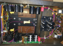
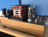
I have two 0.82R 25W power resistors at 3.25A dropping the DC voltage on my 211 heater circuit. They are heat sink type power resistors and bolted to a large 15mm Aluminium plate - see pictures. The whole plate and the Oil filled choke on top of the plate gets to 55 Deg C in a warm day (output transformers on this plate too)- will this be ok for long term durability of the choke and could there be any negative (or positive) impact of this heat on Sound quality.
If it makes any useful difference I have a few ideas but wondered if it's all absolutely fine like this (it has been so far but the summer it seems to get more of a perceived concern)?
Thanks,
If it makes any useful difference I have a few ideas but wondered if it's all absolutely fine like this (it has been so far but the summer it seems to get more of a perceived concern)?
Thanks,
Attachments

"could there be any negative (or positive) impact of this heat on Sound quality"
Of course not ... that is until the point of failure if you boil it.
The choke should be OK up to 70°C.
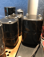
Ps, an oil filled choke is very unusual, oil filled capacitors more common back before electrolytic technology, circa 1950s.
Of course not ... that is until the point of failure if you boil it.
The choke should be OK up to 70°C.
Ps, an oil filled choke is very unusual, oil filled capacitors more common back before electrolytic technology, circa 1950s.
Yeah an old swap/shop sale and they are old!"could there be any negative (or positive) impact of this heat on Sound quality"
Of course not ... that is until the point of failure if you boil it.
The choke should be OK up to 70°C.
Ps, an oil filled choke is very unusual, oil filled capacitors more common back before electrolytic technology, circa 1950s.
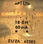
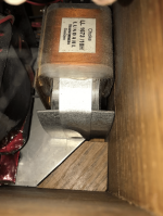
The one on the plate I don't know the value of (out of view label) the other two are 18H 60mA (see label - APT Ltd?)
Attachments
It's worthwhile describing temperatures and power dissipation in a little more detail. Like what was the ambient temperature of the nearby air that cools the amp, and what is the power loss in each choke?
And what is the temperature on the top surface of the choke(s) - as the four mounting bolts at the base may be at 55C, but who knows what is happening inside the chokes as you haven't indicated what is being dissipated in each choke, and what the temp of the outer surface to free air is.
Does the plate get to 55C mainly by the resistor dissipation, or are there other significant parts dissipating via that plate?
If you wanted to chase a rabbit down the sound quality rabbit hole, then the concern would be the increase in DCR of the chokes due to temp - you can estimate that from operating temperature and DCR at a known temperature (ie. cold temp and unpowered). Another concern would be e-cap service life and degrading parameters due to what seems to be only minor ventilation under the chassis.
Start by calculating the actual amount of watts each resistor is adding to the system. Measure the voltage drop across each one and use Ohms Law to calculate the dissipation. It might not be significant in the whole scheme.
A 120mm quiet PC fan, mounted under the chassis, would be a possible solution. I've done that in a couple of amps where chassis size was limited.
A 120mm quiet PC fan, mounted under the chassis, would be a possible solution. I've done that in a couple of amps where chassis size was limited.
Thanks for all the feedback 🙂
The power Watts are approximately 3.25A x 0.82R which is about 9 watts or so on each. The location of the heat source and the outcome of these temperatures is clearly caused by these two resistors. I think as far as temperature management with air that's a possible solution but the challenge is to get the heat away from the aluminium plate that soaks this up (or cool the plate itself more effectively)
The ARCOL data-sheet seems to imply the desired temperature rise of the HS25 at circa 10Watts is around 40 Deg C if I understand the chart correctly?
https://www.ohmite.com/assets/docs/HS-Datasheet.pdf.
Thoughts?
You can use little quiet PC fans like these - https://www.quietpc.com/40mmfans to keep any localised hot components cooler. I've used these to keep mosfets on small heatsinks cool where space was tight, they make a hell of a difference and give you a bit of peace of mind.
Andy.
Andy.
Last edited:
good idea, maybe there are some that are 5V AC and I can steal the supply to the rectifiers?You can use little quiet PC fans like these - https://www.quietpc.com/40mmfans to keep any localised hot components cooler. I've used these to keep mosfets on small heatsinks cool where space was tight, they make a hell of a difference and give you a bit of peace of mind.
Andy.
https://www.quietpc.com/nf-a4x10-5v-pwm this one for example, although it seems to be 5V DC
I would go for the largest fan you can reasonably fit. Small fans are noisier for the same airflow. 2 will be twice as noisy.
I simply rectify the 6.3 volt heater winding and add a 1000uF cap, that gets you about 7 volts DC, plenty for a larger fan. Do not use the 5 volt rectifier winding if it also suppling a rectifier, it will have HT+ volts on it too...
Perhaps a Noctua NF-A12x15 (10.2 dB(A) at 450 revs.?
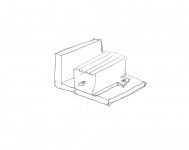
Adding a small right angle of aluminium under the resistor would improve the efficiency as well.
I simply rectify the 6.3 volt heater winding and add a 1000uF cap, that gets you about 7 volts DC, plenty for a larger fan. Do not use the 5 volt rectifier winding if it also suppling a rectifier, it will have HT+ volts on it too...
Perhaps a Noctua NF-A12x15 (10.2 dB(A) at 450 revs.?
Adding a small right angle of aluminium under the resistor would improve the efficiency as well.
Attachments

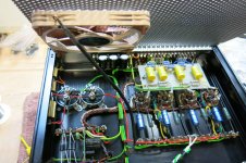
It's simple.I have two 0.82R 25W power resistors at 3.25A dropping the DC voltage on my 211 heater circuit. They are heat sink type power resistors and bolted to a large 15mm Aluminium plate - see pictures. The whole plate and the Oil filled choke on top of the plate gets to 55 Deg C in a warm day (output transformers on this plate too)- will this be ok for long term durability of the choke and could there be any negative (or positive) impact of this heat on Sound quality.
If it makes any useful difference I have a few ideas but wondered if it's all absolutely fine like this (it has been so far but the summer it seems to get more of a perceived concern)?
Thanks,
Use Ohms Law and calculate the wattage requirements needed.
A safe area is 70% of the wattage rating of the resistor(s).
Great, sounds like a plan, I might also start off with a battery and see how the noise and cooling works before moving to a full install 🙂I would go for the largest fan you can reasonably fit. Small fans are noisier for the same airflow. 2 will be twice as noisy.
I simply rectify the 6.3 volt heater winding and add a 1000uF cap, that gets you about 7 volts DC, plenty for a larger fan. Do not use the 5 volt rectifier winding if it also suppling a rectifier, it will have HT+ volts on it too...
Perhaps a Noctua NF-A12x15 (10.2 dB(A) at 450 revs.?
Adding a small right angle of aluminium under the resistor would improve the efficiency as well.
I suppose I could even start off with USB power at 5V from my nearby Macbook?Great, sounds like a plan, I might also start off with a battery and see how the noise and cooling works before moving to a full install 🙂
ahh - thanks, it was actually the heat output from the 25W rated resistor at 10W utility that was generating a warm oil filled Choke and, and warm output transformers that was my concern - all connected to a warm aluminium plate acting as the heat sink for the resistors.It's simple.
Use Ohms Law and calculate the wattage requirements needed.
A safe area is 70% of the wattage rating of the resistor(s).
Warm, able to touch and hold on without uncomfortable feeling, is of not big concern.ahh - thanks, it was actually the heat output from the 25W rated resistor at 10W utility that was generating a warm oil filled Choke and, and warm output transformers that was my concern - all connected to a warm aluminium plate acting as the heat sink for the resistors.
You might also consider removing a couple of turns on the heater winding of the mains transformer - if possible, of course.
I had it on last night again and paid attention to the B+ Voltage which runs through the large oil filled chokes that gets to 50-55 Deg C at the base towards the middle, the top is about 45 Deg C. The rest of the oil filled chokes and caps nearby are 40-45 Deg C. The B+ when first on at 22 Deg C was 999V and at the end of listening was 1004 V (I had wondered if the DC resistance of the choke increased and would result in a slightly lower B+ However this was not the case.)Warm, able to touch and hold on without uncomfortable feeling, is of not big concern.
Just small changes in mains voltage perhaps. Do you know the DC resistance of the choke and how many volts it drops?
All I know is the DC resistance from Rectifier valve to the 211 anode is 572R, and this has 3 chokes in the circuit the oil filled and two of these LL1673/ 10HJust small changes in mains voltage perhaps. Do you know the DC resistance of the choke and how many volts it drops?
Attachments
I used a 12V fan with a simple PWM speed controller on my last build. Was able to lower the speed/noise and still move some air.
- Home
- Amplifiers
- Tubes / Valves
- How hot is too hot?