Hi,
I just repaired a broken guitar combo that I got cheap on Ebay, changeing its dead LM1875 and the filter caps, also I placed those 0,1µF filter caps nearer to the power supply pins, 'cause one of them was some centimeters away. The amp works, but I measured 60°C at cooling pad, while the heat-spreader (oups, right word? you know that aluminium thingie to give the heat to the air) isn't big, but seems big enough.
The other day I build myself a hifi LM1875 (PCB here: http://www.diyaudio.com/forums/attachment.php?s=&postid=1085737&stamp=1166558658)
and the heat spreader was about the same size, but much cooler at about the same volume. Unfortunately I don't own an oscilloscope to check for oscillation...
Would you say that 60°C would rather be normal or do you also think something is wrong here...?
If yes, I'm not sure what to do next.
Across the output of the amp, there's also the recommended cap in series with a resistor (as in the datasheet's circuit).
Cheers,
Dominique
That's about the size of my heatsink (thanks, I forgot that expression) too: 9,5 x 4,5 cm, but when built into the combo case, the heatsink is isolated from the amp, but attached to a big peace of metal (which is part of the case).
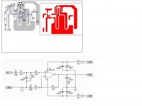
Now I desoldered that stability thingie (Resistor in series with Cap)across the output of the LM1875 and found that the values aren't as recommended in the datasheet.
Datasheet recommends 1 Ohm and 0,22µF while here they used 5 Ohm and 0,1µF.
Could this be the reason for instability?
I don't quite understand why they did so - as a guitar amp doesn't exactly need to be Hifi or High End and could be cut lower, I'd rather be tempted to use a bigger Cap as recommended. The output then is connected to a 4 Ohm speaker.
I'm not really good in electronics laws, but I think I'll try to simulate that to see at which frequencies that sort of filter starts to work...
In my self made hifi circuit with the LM1875, I left that resistor and cap away, still it works fine and cooler. But also my circuit layout is better I think.
Cheers,
Dominique
PS. I attached the datasheet's recommended circuit so you see what stability network I mean...
Attachments
I have build this
http://sound.westhost.com/project72.htm
and no problems with the HeatSkin and the sound is very good, any noise
The PSU are 10 capacitors of 1000 uF each one
I make my own PCB in size of 6 x 8 cms
http://sound.westhost.com/project72.htm
and no problems with the HeatSkin and the sound is very good, any noise
The PSU are 10 capacitors of 1000 uF each one
I make my own PCB in size of 6 x 8 cms
Attachments
In the meantime I found another thing...
Someone messed around in that amp before trying to solder some cables in the reverb section and produced a short circuit. I don't see the connection to the LM1875, cause the short is in the signal path, but now the heatsink is cooler by touch. I'll measure later...
@weissi
hey, you didn't read my introducing text")
I already changed the whole power supply filtering caps, now got better and slightly bigger caps, while I set the small 0,1µF ones nearer to the power supply pins of the IC.
The voltage is ok, something like +-25... 26V
Oh, really 5 Ohm and 0,1µF doesn't make a difference to 1 Ohm and 0,22µF?
Ok, I'll try both, or even 1µF just to see...
@MJS
That's fine that your amp works well! At first sight It looks a bit like my own (see my first post). Edit: At second sight I see you used National's recommended circuit, mostly. That's more secure, but I like it simple. (As long as I don't run across drawbacks)
Cheers,
Dominique
Someone messed around in that amp before trying to solder some cables in the reverb section and produced a short circuit. I don't see the connection to the LM1875, cause the short is in the signal path, but now the heatsink is cooler by touch. I'll measure later...
@weissi
hey, you didn't read my introducing text
I already changed the whole power supply filtering caps, now got better and slightly bigger caps, while I set the small 0,1µF ones nearer to the power supply pins of the IC.
The voltage is ok, something like +-25... 26V
Oh, really 5 Ohm and 0,1µF doesn't make a difference to 1 Ohm and 0,22µF?
Ok, I'll try both, or even 1µF just to see...
@MJS
That's fine that your amp works well! At first sight It looks a bit like my own (see my first post). Edit: At second sight I see you used National's recommended circuit, mostly. That's more secure, but I like it simple. (As long as I don't run across drawbacks)
Cheers,
Dominique
@Dominique: oops, sorry for being a shallow reader 
1µ is to big I guess, stick with 4,7Ohms+0,22µF
@ carlosT : Hmm, for C3 one has to take at least a bipolar electrolytic.... also, you may try to lower the values of the feedback network and completely omit C3. This makes sure that the error voltage is low and therefore also offset voltage (R4=100E). R3 is not essential. If used in connection with a preamp, I would lower R2 to ~10k and increase C1 to 10µ with an additional resistor of ~22k to GND in front of the C1. C7 and C8 should be ~1000µ, which can be mounted close 'cause in this voltage range they are not to big at all (in this case one can omit or lower the main bulk capacitors right after the rectifier).
Personally I would never again build a gainclone without a precision (FET) opamp working as receiver in front of the power opamp. Running the power opamp directly out of the source was in most cases the worst sounding solution (poor output stage, long interconnects, etc.).
But as everyone knows, diy gainclones is a very "esoteric" topic
cheers,
Markus
1µ is to big I guess, stick with 4,7Ohms+0,22µF
@ carlosT
: Hmm, for C3 one has to take at least a bipolar electrolytic.... also, you may try to lower the values of the feedback network and completely omit C3. This makes sure that the error voltage is low and therefore also offset voltage (R4=100E). R3 is not essential. If used in connection with a preamp, I would lower R2 to ~10k and increase C1 to 10µ with an additional resistor of ~22k to GND in front of the C1. C7 and C8 should be ~1000µ, which can be mounted close 'cause in this voltage range they are not to big at all (in this case one can omit or lower the main bulk capacitors right after the rectifier).Personally I would never again build a gainclone without a precision (FET) opamp working as receiver in front of the power opamp. Running the power opamp directly out of the source was in most cases the worst sounding solution (poor output stage, long interconnects, etc.).
But as everyone knows, diy gainclones is a very "esoteric" topic
cheers,
Markus
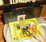
I mounted this with normal components, at that moment i haven´t 1% resistors , in my shop there isn´t all values usually, but i would to try it
Is exactly the same schematic of Elliot´s projects
Carbon resistors 1/4 W, R6 ceramic, and Faco input capacitor
I´m trying various chips and schematics because my intention is to make a 6 channel amplifier
When i decided the chip and the schematic i will buy good components
But this amp sounds very nice, relaxed but nice, better than the LM3886 Elliot´s project that also i have build
I haven´t heat problems, before 3 hours of starting i have 32º C in the heatskin
The transformer is 15-0-15V / 2 A and with the rectification 22,3V
Regards
Attachments

OT - They just busted a guy locally who had a hydroponic setup that was about to go up in flames.
Turns out that this duded had been incarcerated in Philadelphia on unrelated charges and the utility company had turned off the water service. Now you had rooms filled with hot lamps, drying mary-juana plants and automatic fertilizer feeders feeding drying plants under heat lamps...NO WATER
Turns out that this duded had been incarcerated in Philadelphia on unrelated charges and the utility company had turned off the water service. Now you had rooms filled with hot lamps, drying mary-juana plants and automatic fertilizer feeders feeding drying plants under heat lamps...NO WATER
Anyway...to get back on topic. I still don't understand a damn thing about heatsinks other than the bigger the better and you better not ignore the issue
My LM3875 IGC gets nice and warm as does the heatsink and chassis...amazing how much heat "sinks" all the way around. Interesting thing about heat is that the hotter the heatsink gets, the better the heat is transmitted. A single LM3875 had no problem heating up a nice Wakefield 401-K which is 4.75" L x 1.25" H sitting in standard Hammond thin gauge aluminum box.
http://www.wakefield.com/pdf/extruded_heat_sink.pdf
I'm assuming that this is OK.
Yes, I think that heat-sink size should be ok.
PS. That guitar amp now works ok.
When I'll have more time I'll replace some parts (e.g. tone control sounds muddy, so I removed it), but it's ok for now and it get's less hot.
The other day, I got cold feet, then I got the idea to switch my amp on and put my feet on it - worked ok
Cheers,
Dominique
- Status
- This old topic is closed. If you want to reopen this topic, contact a moderator using the "Report Post" button.
- Home
- Amplifiers
- Chip Amps
- How hot does an LM1875 get?