I'm toying around with LTspice and a tube buffer.
When you design a line stage and run sims, what design parameters are you looking for?
When is distortion low enough, what's your target numbers for the bandwidth, how much hum is good (when is it low enough) and so on.
My current sim show that I'm down -0.00032dB at 20Hz, I doubt I can hear a difference if it's 1dB?
Hum is in the 20-30uV region?
Simulations are just an indicator and the finished product can end up being quite different but when you do run simulations what are your target numbers and what are you looking for?
I would not trust simulations for distortion figures personally. It might show if you have something grossly out of whack but I don't trust the models well enough to put much faith in the resulting numbers.
It depends on why you want a line stage. Some people want 'tube sound', so you design for, say, 0.5% distortion and an HF droop. Others want to drive a long interconnect so you design for low distortion and low output impedance.
mashaffer> Like I said, I don't regart sims as gospel truth. I see it as an indication where I'm heading...
DF96> I'm still learning LTspice and distortion is still something I don't know how to simulate. Bandwidth I can do and my current data is mentined above, I don't know what I'm supposed to be aiming for though? Straight as an arrow in HF range and a very small (-0.00032dB) drop in the LF.
I'm not entirely sure how to simulate hum/background noise? Doing it the easy (possibly wrong) way by turning off the signal show noise in the 20-30uV area. Still I don't know if I'm doing it right or wrong or even if the numbers are awsome or sucky?
To me all the numbers seem to good to be true and I figure this will change when I build the actual circuit irl.
Thus the question, how good is good? I don't even know how much ripple I should aim for on the B+?
I figure -60dBu noise on the output should be pretty much inaudiable? Beyond that I'm undecided? Looking for info from you guys who've done this longer than I. 🙂
Simulating hum is difficult, because some major sources of hum do not appear in the circuit diagram. You can simulate supply rail ripple, but not induction from the heater circuit.
My guess is that you want noise and hum to be at least -80dB below the normal peak output (which you need to determine). Don't worry too much about distortion, unless it is high (above 1%) - this would indicate clipping or a bad bias point. However, the first stage of design is to decide what your requirements are. If you ask us what our requirements are you will get a lot of different answers. The 'standard engineering' answer might be 20-20kHz at better than -3dB, less than 0.1% distortion. Some will tell you that this is nowhere near good enough, you need 10-30kHz at -1dB and 0.0001% distortion; others will say that these are irrelevant specs - such people might be happy with a 'tuned' frequency response and 5% distortion as long as it is low order.
Just as you need to decide what your favourite food is, you need to decide what 'audio school of thought' you will follow. Some ideas are supported by scientific evidence, but even this is disputed - some think better tests are needed, others reject the idea of testing. To put it bluntly, some design with their calculator while others design with their ears. I am not trying to start a debate here, just alerting you to the background to what seems like a simple question. You can find the debate in other threads.
Great summary of what's going on here. Yeah, it doesn't take long to know what people are about. Golden eared (mystical visionaries) camp vs scientific camp whose motto "I trust my distortion analyzer, not my ears" is all over the place. Unfortunately, one has to read it every day. It may be excellent in its objectivity but it really gets tiresome.. Some will tell you that this is nowhere near good enough, you need 10-30kHz at -1dB and 0.0001% distortion; others will say that these are irrelevant specs - such people might be happy with a 'tuned' frequency response and 5% distortion as long as it is low order.
Just as you need to decide what your favourite food is, you need to decide what 'audio school of thought' you will follow. Some ideas are supported by scientific evidence, but even this is disputed - some think better tests are needed, others reject the idea of testing. To put it bluntly, some design with their calculator while others design with their ears.
Last edited:
I've been around for a while so I know exactly what you're referring to.
I would like to think of myself somewhere in the middle.
Yes, the ears are the final judges but good engineering and measurments are tools that help you achieve hifi-bliss. 🙂
What I'm looking for are minimum requirements.
Stuff like
- 2mV B+ ripple is generally ok
- +/- 1dB @ 20-20kHz is good enough that you'll probably not notice it
- -80dBu ripple/noise at the output will probably percieved as a "silent" preamp
Minimum requirements and rules of thumb that tell you when it's time to stop simulating and start building.
The final performance will always be determined in the lab, not in front of a computer screen and a spice simulation.
such people might be happy with a 'tuned' frequency response and 5% distortion as long as it is low order.
Care to name any such hypothetical people? Or any preamps which have been designed for 5% distortion and 'tuned' response? Or is this simply your fictional idea of what a demented audiophile should be?
asa, I don't think DF96 was 'pointing the bone' at anyone, just using a hypothetical spread of differing views to highlight his point that you need to first determine your design goals. Work out is what it is that makes you happy, then you can design for it.
5% distortion, mainly second order, will be common at high volumes for a SET amp. There are those, both DIY and commercial, who admit to 'tuning by ear' an RIAA network. I did not use the word "demented". I am not trying to start a debate, but explain why answering the OP's question is not straightforward.
Allowed levels of supply ripple depend on allowed levels of hum in the output and the PSRR of the circuit. You start from the output, and work your way back to what supply ripple you need, then include a safety factor. Acceptable hum/noise levels depend partly on whether you are before or after the volume pot - you might want 20-30dB better after the pot so you can turn down the music without hearing noise.
Allowed levels of supply ripple depend on allowed levels of hum in the output and the PSRR of the circuit. You start from the output, and work your way back to what supply ripple you need, then include a safety factor. Acceptable hum/noise levels depend partly on whether you are before or after the volume pot - you might want 20-30dB better after the pot so you can turn down the music without hearing noise.
Since this is a learning experience for me I'll update when I make relevant advances.
I have no clue if this is any good but I'll post it anyway. The figures are scary looking to me...
Harmonic Frequency Fourier Normalized Phase Normalized
Number [Hz] Component Component [degree] Phase [deg]
1 1.000e+03 6.599e-01 1.000e+00 -179.63° 0.00°
2 2.000e+03 4.084e-04 6.189e-04 124.15° 303.78°
3 3.000e+03 1.393e-02 2.111e-02 16.15° 195.78°
4 4.000e+03 3.522e-04 5.336e-04 157.61° 337.23°
5 5.000e+03 6.857e-04 1.039e-03 86.91° 266.53°
6 6.000e+03 2.730e-04 4.137e-04 -171.10° 8.53°
7 7.000e+03 2.330e-04 3.531e-04 116.08° 295.71°
8 8.000e+03 1.889e-04 2.862e-04 -144.69° 34.93°
9 9.000e+03 9.753e-04 1.478e-03 106.09° 285.72°
Total Harmonic Distortion: 2.121622%
Looking at the FFT graphics the peak background noise measures as -70dB.
Better B+ filtering should lower this?
You appear to have a bad, and lumpy, HF cut and highish distortion.
Is the FFT floor a genuine noise floor, or just accumulated rounding errors from the algorithm? I am not familiar with the software you are using. I doubt if it can simulate B+ noise; B+ ripple yes, but not noise as that depends on how clean your mains supply is.
Is the FFT floor a genuine noise floor, or just accumulated rounding errors from the algorithm? I am not familiar with the software you are using. I doubt if it can simulate B+ noise; B+ ripple yes, but not noise as that depends on how clean your mains supply is.
My bad. 
You are correct, I should have said B+ ripple.
It's hard to estimate rounding errors since I have to avoid getting "time step to small" errors.
I'll try improving on accuracy and see if I can get the B+ ripple down.
I have to start somewhere...
You are correct, I should have said B+ ripple.
It's hard to estimate rounding errors since I have to avoid getting "time step to small" errors.
I'll try improving on accuracy and see if I can get the B+ ripple down.
I have to start somewhere...
If the Fourier is for a linestage it is no fun at all(said mildly), as the odd-order harmonics grossly dominate!
Last edited:
Back to the drawing board.
There's something seriously wrong with my results.
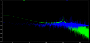
The terrible FFT for the output actually mimics the input. A shoddy source will give you a bad result.
I'm still learning the software...
A picture is worth a thousand words. The green is the output and the blue the input.
There's something seriously wrong with my results.
The terrible FFT for the output actually mimics the input. A shoddy source will give you a bad result.
I'm still learning the software...
A picture is worth a thousand words. The green is the output and the blue the input.
Attachments
In LTspice you need to set a few options (like getting rid of the data compresion) for the FFTs ( and therefore the distortion numbers) to be accurate. Search the Splce help for how to do this.
It would appear the FFT results are somewhat random?
After some tweaking of the settings I get THD ranging from 0.001% to 0.6%, this here being the best result so far. (I get this kind of result most frequently, 0.001xx%)
Harmonic Frequency Fourier Normalized Phase Normalized
Number [Hz] Component Component [degree] Phase [deg]
1 1.000e+03 6.364e-01 1.000e+00 -180.00° 0.00°
2 2.000e+03 2.125e-06 3.339e-06 123.82° 303.82°
3 3.000e+03 6.640e-06 1.043e-05 171.60° 351.60°
4 4.000e+03 9.260e-07 1.455e-06 132.43° 312.42°
5 5.000e+03 7.571e-07 1.190e-06 131.71° 311.70°
6 6.000e+03 6.821e-07 1.072e-06 129.88° 309.87°
7 7.000e+03 6.454e-07 1.014e-06 127.59° 307.58°
8 8.000e+03 6.406e-07 1.007e-06 123.39° 303.39°
9 9.000e+03 6.952e-07 1.092e-06 117.45° 297.45°
Total Harmonic Distortion: 0.001131%
Regardless of the details, could one say I'm in the right region now? Aiming for something like 0.1% THD? This'll give me a fighting chance when I build the circuit?
Although my sim show me less than 2mdB drop over the frequency range (AC analysis) I should have a fairly big margin until it becomes audiable.
Like I said in the beginning, I like to see the sim as a way of avoiding major issues.
Thus I'm trying to figure out where to draw the line and just go ahead and build it. 🙂
There's some time and money involved so staying clear of major pitfalls is an issue.
I found that about 45dB down of 2nd harmonic can sound pleasant  (tube warmth), but you really don't want to hear any 3rd harmonic (keep it below say 60dB down). But if the 2nd harmonic gets too high, more complex or busy music can get muddy, from intermodulation distortion products.
Agreed that simulations are not the final word, but they are useful in that you can identify dumb errors in design. So you can avoid wasting too much solder. 🙂
(tube warmth), but you really don't want to hear any 3rd harmonic (keep it below say 60dB down). But if the 2nd harmonic gets too high, more complex or busy music can get muddy, from intermodulation distortion products. Agreed that simulations are not the final word, but they are useful in that you can identify dumb errors in design. So you can avoid wasting too much solder. 🙂
- Status
- Not open for further replies.
- Home
- Amplifiers
- Tubes / Valves
- How good is good enough when designing a line stage?