+/-50V supplies would be a wasted if only one pair of output transistors were necessary. Fine for class AB but think of requiring Amperes of bias current for class A. More sensibly, reduce the wasted power by reducing the rail voltages to what would be sufficient for perhaps 15W-20W/4R in class A.
Dear friend, you're right.+/-50V supplies would be a wasted if only one pair of output transistors were necessary. Fine for class AB but think of requiring Amperes of bias current for class A. More sensibly, reduce the wasted power by reducing the rail voltages to what would be sufficient for perhaps 15W-20W/4R in class A.
Since I didn't design it, I don't know whether it's reasonable to reduce the voltage
That's a sensible reply but by the same reasoning, why are you considering a class AB design for 50-100W, to be adapted to class A operation at much lower power output? There is an important and different set of requirements for the thermal design of class A, AB and other hybrid classes of amplifier and it needs careful planning with regard to the expensive hardware.
May I suggest that for class A you should start with a 15-20W class A amplifier design and then listen and decide why you would need to begin with an over-complex AB design. As examples, the JLH 10-15W class A amp and later versions with a little more power output or ESP (Rod Elliott's) DOZ design, are simple but hard to beat for sound quality, once fitted with good quality components and enough heatsink to prevent burns to you. 15W in class A gets real hot unless you have large heatsinks and/or fans. - as you might fit in 100-150W class AB amplifiers. .
.
May I suggest that for class A you should start with a 15-20W class A amplifier design and then listen and decide why you would need to begin with an over-complex AB design. As examples, the JLH 10-15W class A amp and later versions with a little more power output or ESP (Rod Elliott's) DOZ design, are simple but hard to beat for sound quality, once fitted with good quality components and enough heatsink to prevent burns to you. 15W in class A gets real hot unless you have large heatsinks and/or fans. - as you might fit in 100-150W class AB amplifiers.
.
Last edited:
Dear friend, you're right.
Since I didn't design it, I don't know whether it's reasonable to reduce the voltage
Here Is A Suggestion For You You Can Try This Version Here Is Schematic Class Ab Amp..Dear friend, you're right.
Since I didn't design it, I don't know whether it's reasonable to reduce the voltage
Attachments

Yes, Zohaib. That is a similar sized power amplifier kit design to the OP schematic design but can it work in class A without burning up? Will it function at lower power supply voltages as necessary to operate it safely? I think it will actually have the same problems. I also think it's time to read up on class A power amplifier design, focusing on bias current demand and the practical heat dissipation limits of power transistors.
After receiving the circuit diagram you sent, I think it looks very good. Thank youYes, Zohaib. That is a similar sized power amplifier kit design to the OP schematic design but can it work in class A without burning up? Will it function at lower power supply voltages as necessary to operate it safely? I think it will actually have the same problems. I also think it's time to read up on class A power amplifier design, focusing on bias current demand and the practical heat dissipation limits of power transistors.
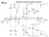
This is the design drawing sent to me by a friend. He said it sounds good, but after listening to your advice, I think it may not be perfect,Yes, Zohaib. That is a similar sized power amplifier kit design to the OP schematic design but can it work in class A without burning up? Will it function at lower power supply voltages as necessary to operate it safely? I think it will actually have the same problems. I also think it's time to read up on class A power amplifier design, focusing on bias current demand and the practical heat dissipation limits of power transistors.
Thank you for your advice
Comments on multiple posts:This is the design drawing sent to me by a friend. He said it sounds good, but after listening to your advice, I think it may not be perfect,
Thank you for your advice
No amp is perfect. Some are terrible, some very good, a lot are "fine" Many tradeoffs depending on your preference. With the latest generation of class D which measure "classical" parameters well below the theory says we can hear, the tend to sound "sterile" to me yet some claim them to be "perfect" Far better than earlier ones that sound down right harsh. In linear amps, one can tailor the sound depending on which defects you find most tolerable. Perfect is what sounds best to you and no one can tell you what you hear or prefer.
Audio through LTSpice? Useless. Sorry. The sound you will get is your PC DAC/Soundcard and amplifier which may be far worse than the circuit in simulation unless it is absolutely horrible. Kind of like the U-Tube reviews of speakers that play the sound for you. I guess there are some folks that fall for that.
Why two voltages for the rails? The VAS will clip at a lower voltage, so the higher VAS voltage allows driving the outputs closer to clipping. A topic covered in the Self and Cordell books. Usually not done unless one also regulated the IPS/VAS rails so building a second power supply anyway. Not very common as very expensive for marginal gains.
Again, as many have suggested, go do your homework. Read the books. Understand the circuit and why one topology may differ from another. Do not rely on some friend who says it is great unless his name is Curl, Pass, Cordell, Self, Diddon... Amplifier design is real engineering. If you are unwilling to do this, then just go buy an amp. Maybe check out Elliot Sound Products amp boards. The small MOSFET is pretty nice, but as I said, I am partial to MOSFET amps. Lots of good information though. Do understand, the schematic is only half the story. The board layout, power and ground topology, specific component selection etc. all matter. A 1K resistor is not just a resistor. All parts have multiple parameters that can effect the sound.
I Am Agree With You As You Said No Amp Is Perfect. I Agree With You..Comments on multiple posts:
No amp is perfect. Some are terrible, some very good, a lot are "fine" Many tradeoffs depending on your preference. With the latest generation of class D which measure "classical" parameters well below the theory says we can hear, the tend to sound "sterile" to me yet some claim them to be "perfect" Far better than earlier ones that sound down right harsh. In linear amps, one can tailor the sound depending on which defects you find most tolerable. Perfect is what sounds best to you and no one can tell you what you hear or prefer.
Audio through LTSpice? Useless. Sorry. The sound you will get is your PC DAC/Soundcard and amplifier which may be far worse than the circuit in simulation unless it is absolutely horrible. Kind of like the U-Tube reviews of speakers that play the sound for you. I guess there are some folks that fall for that.
Why two voltages for the rails? The VAS will clip at a lower voltage, so the higher VAS voltage allows driving the outputs closer to clipping. A topic covered in the Self and Cordell books. Usually not done unless one also regulated the IPS/VAS rails so building a second power supply anyway. Not very common as very expensive for marginal gains.
Again, as many have suggested, go do your homework. Read the books. Understand the circuit and why one topology may differ from another. Do not rely on some friend who says it is great unless his name is Curl, Pass, Cordell, Self, Diddon... Amplifier design is real engineering. If you are unwilling to do this, then just go buy an amp. Maybe check out Elliot Sound Products amp boards. The small MOSFET is pretty nice, but as I said, I am partial to MOSFET amps. Lots of good information though. Do understand, the schematic is only half the story. The board layout, power and ground topology, specific component selection etc. all matter. A 1K resistor is not just a resistor. All parts have multiple parameters that can effect the sound.
On The Other Hand Not About just About Amp It Is Just About Everything Mean Nothing Is Perfect In The World. You Have To Make It Perfect For Your Self.. You Should must Take An Advice From Experienced Person Than You Should Try To Build Some Thing..
If You Like Some Thing Mean Amp Quality Or a sound Etc.. You Will Suggest It to Other Persons Bcoz It Works For you..It Is Perfect For you ..
Sorry for Bad English .
I wanted to write long And Huge But I Cant Due To Some Work...Ok Thanks I Just wanted To Say that..👍🏻
Last edited:
Yes, you said it very wellComments on multiple posts:
No amp is perfect. Some are terrible, some very good, a lot are "fine" Many tradeoffs depending on your preference. With the latest generation of class D which measure "classical" parameters well below the theory says we can hear, the tend to sound "sterile" to me yet some claim them to be "perfect" Far better than earlier ones that sound down right harsh. In linear amps, one can tailor the sound depending on which defects you find most tolerable. Perfect is what sounds best to you and no one can tell you what you hear or prefer.
Audio through LTSpice? Useless. Sorry. The sound you will get is your PC DAC/Soundcard and amplifier which may be far worse than the circuit in simulation unless it is absolutely horrible. Kind of like the U-Tube reviews of speakers that play the sound for you. I guess there are some folks that fall for that.
Why two voltages for the rails? The VAS will clip at a lower voltage, so the higher VAS voltage allows driving the outputs closer to clipping. A topic covered in the Self and Cordell books. Usually not done unless one also regulated the IPS/VAS rails so building a second power supply anyway. Not very common as very expensive for marginal gains.
Again, as many have suggested, go do your homework. Read the books. Understand the circuit and why one topology may differ from another. Do not rely on some friend who says it is great unless his name is Curl, Pass, Cordell, Self, Diddon... Amplifier design is real engineering. If you are unwilling to do this, then just go buy an amp. Maybe check out Elliot Sound Products amp boards. The small MOSFET is pretty nice, but as I said, I am partial to MOSFET amps. Lots of good information though. Do understand, the schematic is only half the story. The board layout, power and ground topology, specific component selection etc. all matter. A 1K resistor is not just a resistor. All parts have multiple parameters that can effect the sound.
Now I give up making this circuit and try to use class D amplifier. The new class D amplifier has excellent parameters and low calorific value, which is very suitable for my working environment
beholden!
Okay good I will wish to see your class d amp circuit diagram when you create it kindly share it with us thanks.Yes, you said it very well
Now I give up making this circuit and try to use class D amplifier. The new class D amplifier has excellent parameters and low calorific value, which is very suitable for my working environment
beholden!
- Home
- Amplifiers
- Solid State
- How does this circuit structure sound