Hi, I am looking for some advice as to how the Electra-print's DRD Ultrapath works. Specifically, I am looking at the 45 version.
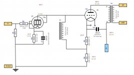
The 7k5 resistor sets the voltage for the Driver tube. In the schematic it is 180V. So the real value of the 7k5 adjustable should be 3k6 assuming 50mA through it. If the 7k5 resistor is providing 180V for the driver, then the B+, in the conventional sense, of the 45 tube is around 320V, allowing for other resistance losses, say 300V.
What I don’t understand now, if the 2k and 7k5 string has 50mA through it, surely the 45 is now biased at 50mA/300V. Which is well above it the idle current limits and Plate dissipation, so am I missing something?
What I thought the operating points of the 45 was; 300V between plate and cathode, -47V bias and 30mA. This gives a cathode resistor of 1k5, and puts it right at the limit of the 45, and at full input of 0v grid, almost 2.7W of power.
Now, am I missing something? The 50mA as set by the cathode resistor strings, and the actual bias current of the 45 tube?
The other scenario is assuming that 15mA is going for the driver tube, that leaves the 45 at 35mA. This changes it to slightly higher plate dissipation at almost 9W and a cathode resistor of 1k29 and bias of -45V. But the question is, isn’t the current constant from the transformer through to ground as it runs through the cathode resistor string?
Then the next question is that, is the bias of the 6AN4 180V at 12-15mA. This doesn't make sense as it means that the grid bias is -1V, which means that the cathode resistor should be 80R, but it is 150R.
Someone please help!!!!
Am I missing something here?
I read that as "0.5V = 50 mA", not that the idle current is 50 mA.
The 10R resistor is obviously there for easier voltage read-out (which trabnslates directly into current with the given factor).
The 10R resistor is obviously there for easier voltage read-out (which trabnslates directly into current with the given factor).
Looking back at this and reading some more, I think I might have worked this out, but just want to double check with others. The 2k adjustable resistor sets the bias for the 45. Dial in whatever one wants to get the right conditions for the 45 as desired. The lower 7.5k resistor's sole purpose is to set the voltage for the driver stage.
A scenario, if I wanted the 45 biased at 260V, -46.5V at 36 mA, the 2k variable resistor should be set to around 1k3 (V=IR => 46.5 = 0.036 x R). If I want the driver stage to be have around 190V, then the 7k5 variable resistor would need to be set at around 5k3 (V=IR => 190 x 0.036).
Am I understanding it correctly?
If I want the driver stage to be have around 190V, then the 7k5 variable resistor would need to be set at around 5k3 (V=IR => 190 x 0.036).
Note that the current consumed by the driver is subtracted from the current through the #45. If you have 36mA through the #45 and let's say 10mA through the driver, there will be 26mA left to flow to ground to the adjustable 7k5 resistor. It's value should then be 190/0,026 = ~7k3
The attached is my stab at understanding how the DRD works, appreciate if anyone can chime in with their thoughts, and corrections. I have assumed generalised voltage drops over the transformers and resistors, obviously fine tuning will be required once built. Thanks!
Attachments
I can't spot any problem. Indeed, the choke will cause some additional voltage drop, and 2V is maybe too little, but you can adjust for that!
Thanks for that. I might adjust for an extra 5 or 10 volts. Will be laying out the chassis soon, cheers.
That is a weird circuit! Seems designed to sell iron and act as a room heater. Why don't they use a negative supply for the first stage, instead of throwing away much of the power from a big positive supply?
Of course it's designed to sell iron... 🙂
But actually, using magnetics is a very good sounding way to make audio circuits. There have been many engineering feats and circuits designed to eliminate iron from circuits, purely because it's so darn expensive... However, in DIY, a bunch of iron is affordable if we choose to use it. In a commercial product, with a 4x cost to retail ratio, eliminating expensive and heavy transformers and chokes saves a ton of money to the end user.
I have built and had Ultrapath amps and preamps. The circuit is very sweet, detailed, articulate, and most of all, musical. You will like it!
But really how much extra iron is there? Just the driver choke, and they weren't too expensive at all. The parafeed designs chokes are more expensive., as are interstages as well.
But looking forward to building it soon!
But looking forward to building it soon!
- Status
- Not open for further replies.
- Home
- Amplifiers
- Tubes / Valves
- How does DRD Ultrapath Work?