I am considering a design using two woofers in parallel. I would probably use one Zobel RC network in parallel with the two woofers to flatten the impedance curve and a series resistance between the amplifier (solid state with very low output Z) and the Zobel network to both attenuate the woofer pair slightly and to raise their Qts value. My problem is that I don't know how the series R will interact with the Zobel RC to affect the frequency response of the woofers, or if it will affect them at all.
I would probably use a series Z of no more than 2 or 3 ohms, including the crossover coil also in series. Is this a significant enough resistance to react with the Zobel and give a high-frequency rolloff, and is there a formula one can use to calculate the rolloff?
Any technical information or applicable links will be much appreciated. Thanks to all.
RC Zobels are primarily used to flatten impedance at higher frequencies associated with the inductance of the driver(s). If your particular Zobel achieves that well then the impedance will remain relatively flat at high frequencies and an additional series resistor will yield a simple attenuation......at those higher frequencies.
Dave.
Dave.
That series resistor will have to be pretty large in able to handle the power going through it to both woofers. Usually not a good idea to try to attenuate woofers like that.
Loj,
the left shows F-3dB roll off as being at 2kHz. Does 2.000Hz = 2kHz, or does 2.000Hz equal 2Hz?
But the blue line is down by 8dB @ 2kHz using the 1mH inductor as an L+R single pole filter.
Can you explain where the 5dB has gone?
the left shows F-3dB roll off as being at 2kHz. Does 2.000Hz = 2kHz, or does 2.000Hz equal 2Hz?
But the blue line is down by 8dB @ 2kHz using the 1mH inductor as an L+R single pole filter.
Can you explain where the 5dB has gone?
The 5db comes because he changed the DCR from 0.5 ohms to 3.0 ohms.
I think the OP's objective here is not to attenuate the woofers, but alter the system Qts. This is not the way I'd do it, but that wasn't his question.
Cheers,
Dave.
I think the OP's objective here is not to attenuate the woofers, but alter the system Qts. This is not the way I'd do it, but that wasn't his question.
Cheers,
Dave.
Andrew,
2.000 Hz = 2kHz and has no meaning in simulations posted.
If one would want the spreadsheet to calculate textbook
values for a certain XO point, that would be the place to
define it. I chose the values with no special reason, except
desired series R= dcr.
2.000 Hz = 2kHz and has no meaning in simulations posted.
If one would want the spreadsheet to calculate textbook
values for a certain XO point, that would be the place to
define it. I chose the values with no special reason, except
desired series R= dcr.
The left shows 0r50The 5db comes because he changed the DCR from 0.5 ohms to 3.0 ohms.
I think the OP's objective here is not to attenuate the woofers, but alter the system Qts. This is not the way I'd do it, but that wasn't his question.
Cheers,
Dave.
The right shows 3r00
The left has the missing 5dB @ what I presumed was the roll-off frequency.
Andrew,
I'm confused I guess, or the photo's are switched, or something. I see the response with the 0.5 DCR as nominally 90db and the response with 3.0 DCR as nominally 85db. (In the 100-1000hz decade.)
Higher up in frequency the inductive reactance starts to dominate the DCR and the response becomes essentially the same......near the roll-off frequency.
Am I not looking at it correctly?
To me, what Lojzek has posted looks perfectly believable.
Cheers,
Dave.
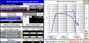
The photo on the left represents 2 drivers wired in parallel.
The upper response is without inductor and Zobel, the lower
with 1,0 mH( dcr 0,5 ) and Zobel (10 uF, 4 ohm).
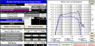
The photo on the right is the same as the one on the left, with
only difference of increased inductor's dcr to 3 ohms.
The upper response is without inductor and Zobel, the lower
with 1,0 mH( dcr 0,5 ) and Zobel (10 uF, 4 ohm).
The photo on the right is the same as the one on the left, with
only difference of increased inductor's dcr to 3 ohms.
Last edited:
R ohm = 4.00 tells us you paralleled two 8ohms drivers !!!! you could have warned us.
What does "C uF = 10.00" tell us?
Could you repeat the plot?
with three graphs.
driver response alone.
driver + inductor (0r5)
driver + Zobel + inductor( 0r5)
and then driver + inductor (3r0)
driver + Zobel + inductor (3r0)
What does "C uF = 10.00" tell us?
Could you repeat the plot?
with three graphs.
driver response alone.
driver + inductor (0r5)
driver + Zobel + inductor( 0r5)
and then driver + inductor (3r0)
driver + Zobel + inductor (3r0)
Andrew,
The R value of Zobel only tells that I chose one of 4 ohms,
and the same applies to 10 uF. OP said he wanted to find out
how would series R interact with Zobel, so I simulated exactly
two drivers in parallel with arbitrary values for inductor and Zobel.
How would you want me to simulate Vifa PL 18? As a single driver?
Last edited:
Thanks to Lojzeck for the illustration and to everyone else for their comments. I will tell you all what I am considering:
Some time ago I obtained a pair of Tang Band W5-1611SAF drivers based upon the factory specifications and positive reviews from users. I auditioned them mounted in sealed enclosures and liked what I heard. I had originally thought to use them in some kind of ported enclosure, but I eventually decided to use them in a sealed box as the main driver in a FAST construction. I decided to try them crossed at the baffle step frequency of 400Hz to a woofer with a first-order series network. The woofer I chose was the Peerless 8 inch Nomex HDS-P830869 which I would mount in a bass reflex cabinet.
When I examined various means of attenuating the W5-1611 to match to the Nomex 8 at baffle step, I found that the Qts of the Tang Band, which was already at a fairly high value, got too high for a smooth low-end rolloff in a reasonably small chamber, so I thought I might use two Nomex 8 in parallel instead of attenuating the W5-1611. When I looked at possible attenuation for the Nomex 8 pair, I found that using a series resistance would not only attenuate the two woofers enough so that they did not overpower the Tang Band, but also raise the Qts value enough so that I could use the parallel woofers in a sealed enclosure, which I would prefer to the BR box. I understand that any resistors I use must have a sufficient power rating for any likely wattage I might run through them. My main area of uncertainty was the possibility of altering the nice flat response of the Nomex 8 to the point where I would not achieve the first-order HF rolloff that I want.
After my original post, I tested various Zobel combinations on the paralleled Nomex 8 drivers with my impedance tester, and I found that a network of 33mfd capacitor and 4.3ohms resistor gave a very flat impedance curve with a value of 3.5ohms from 100Hz to 10kHz. Would Lojzek or another generous DIY member care to run a simulation with the values for two Nomex 8 drivers, the Zobel I mentioned, and 1, 2, and 3 ohms inline resistance? And, since my knowledge of filter theory is basic at best, is there any way to manually compute a possible high-frequency rolloff with a series resistance between the amplifier and the Zobel network? F3 = 1/2PiRC seems too simple somehow. Thanks to anyone who can help.
Last edited:
I am trying to understand the effect of the added series R.
The plots help a lot, but I was confused with the way the info was presented.
I think I now know what was presented.
The plots help a lot, but I was confused with the way the info was presented.
I think I now know what was presented.
Would Lojzek or another generous DIY member care to run a
simulation with the values for two Nomex 8 drivers, the Zobel
I mentioned, and 1, 2, and 3 ohms inline resistance?
It would not be any trouble to simulate what you want if I had the
needed frd and zma files of Peerless Nomex 8 drivers. I tried once
to use SPL tools program to make these out of manufacturer's
graphs, but failed to do a proper job.
Thanks, Lojzek, for the offer, but after sleeping on the idea and playing with the box modeling software I have decided to return to my original idea of using one Nomex 8 in a ported box and attenuate the W5-1611. Trying to make two woofers work was creating too many problems, and upon reflection, I believe that a slight low-frequency boost from a higher Qts value on the Tang Band driver might work out fine. When I build the speaker I'll post listening impressions and some photos.
Last edited:
- Status
- Not open for further replies.
- Home
- Loudspeakers
- Multi-Way
- How does a series R interact with a Zobel RC?