I'm no expert on regulator tubes but I know that using them as a shunt is big the tip of the iceberg. They are really meant to be used in active regulators in combination with other tubes...
If voltage regulator tubes could not serve as shunt regulators but only as voltage reference tubes as part of a regulated/stabilized power supply, than why so many of them have a relatively high maximum current? Note that as a voltage reference tube in a regulated power supply they could do the job while passing just a few of mA.
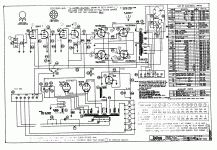
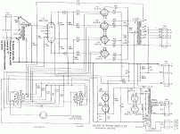
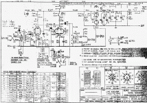
Attached are some examples of mostly profesional equipment with the 0D3 (or the 0A2 in the microphone amplifers of the EMI REDD.47 mixing console) as shunt voltage regulators. In some of them they are used to feed screen grids of power tubes. And there are many more examples (see post #118 for an example with 2 x ZZ1040).
Addition: Here you can find more equipment in which the 0D3 is being used: 0D3, Tube 0D3; Rohre 0D3 ID4081, Voltage Regulator, single
Attachments
-
 2 x 12AU7 dc-coupled + 4 x 7867 pp + 2 x 5U4GB + 0D3 (Dukane 1A475C).gif195.7 KB · Views: 270
 -
Transformer-coupled 2 x 6J7 + 4 x 807 pp + 5R4GY + 2 x 0D3 (RCA MI-12245).pdf2.5 MB · Views: 125
-
 Transformer-coupled 6SL7 + 4 x 6L6G pp + 2 x 5U4G + 0C3 + 0D3 (RCA MI-9377).gif99.2 KB · Views: 270
 -
 6SL7 + 4 x 807 pp + 5R4 + 2 x 0D3 (RCA MI-12188A).gif170 KB · Views: 317
 -
 Transformer-coupled EF86 + ECC88 para parafeed opt + 2 x 0A2 (REDD.47).gif287.9 KB · Views: 260
 -
D3a + KT88 ul se + 2 x 6CJ3 + 0D3 (Pete Millett).pdf31.2 KB · Views: 123
Last edited:
Old technology is quite interesting and in that period in time it functioned very well. Maybe that is why some of us choose to incorporate the ancient technology in some of our DIY projects. In addition to working quite well it has that aesthetic pleasing look that a Zener simply cant provide.
PFL200,
Using a gas voltage reference tube within its minimum current and maximum current limits can cause the screen voltage to vary (even if the tube current varies only a few mA).
That means the reference voltage is not constant as the screen draws varying amounts of current to the dropping resistor that feeds the voltage reference.
That is the reason to use a control tube and a pass tube circuit. That kind of regulator circuit is designed to present a constant current to the voltage reference tube; and so the reference voltage is reasonably constant.
But, things like varying B+ that supplies the current through the dropping resistor, and largely varying ambient temperature may change the reference voltage.
Your Mileage May Vary.
Last edited:
Sorry, but I don't believe this to be true. That is why earlier I asked you for an explanation or a source that backs your statement. Why would the screen voltage vary?
I notice that now you use the term "voltage reference tube" while in post #133 you used the term "regulator tube". But that doesn't really change things since the 0D3 is more a voltage regulator tube than a voltage reference tube.
If you look at the graph on the last page of this datasheeet for the ZZ1040 you will see that the voltage over the ZZ1040 stays very stable over the range of 5 mA to 60 mA. Without further explanation, I really don't see why this graph would not hold if the load would be varying like it would when the load are two screen grids.
https://frank.pocnet.net/sheets/128/z/ZZ1040.pdf
PFL200,
Take a 300V supply, a 7500 Ohm series resistor to the OD3 plate, and the OD3 cathode to ground.
Connect a 50000 Ohm resistor to ground, and the other end of the resistor to the junction of the 7500 Ohm resistor and the OD3 plate. That is a 3mA load on the 150V reference.
Now, connect a 15000 Ohm resistor across the 50000 Ohm resistor. That is a 10mA load on the reference (13mA total). The 150V reference voltage will go down by about 1V.
The following example is only to represent a pentode or beam power tube, for illustration of the concept.
Find a tube data sheet graph that plots screen current g2, versus g1 voltage, and plate voltage.
Look at screen current of a pentode or beam power tube, with constant screen g2 voltage; and g1 grid voltage starting at -20V quiescent, and with signal swinging g1 to 0V, the g2 current will increase.
So, if you use a 300V B+, 7500 Ohm resistor, and OD3 to power an output tube screen, g2, and when the signal to the output tube causes the quiescent screen current of 3mA to go to 13mA, the 150V reference will go down by 1V, and the screen voltage will go down by 1V.
Not all gas discharge tubes are exactly the same. But the OD3 with a current that varies from 5mA to 40mA will change its ionized voltage by 4V.
If that is not clear, build it and see the result.
Last edited:
OK, thanks. I thought that you were referring to larger voltage changes than the maximum difference of 4 volt for the 0D3.
I agree with you that gas discharge tubes are not exactly the same. The ZZ1040 (a tube that was developped much later than the 0D3) does not show a voltage change over its whole range of 5 to 60 mA. So when using the ZZ1040 (inside its limits) for feeding screen grids, the screen grid voltage will not vary.
I agree with you that gas discharge tubes are not exactly the same. The ZZ1040 (a tube that was developped much later than the 0D3) does not show a voltage change over its whole range of 5 to 60 mA. So when using the ZZ1040 (inside its limits) for feeding screen grids, the screen grid voltage will not vary.