Just adding another cat skin to the list.
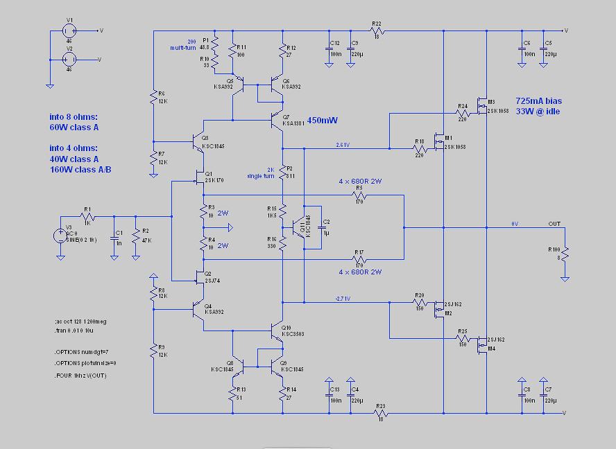
If you’re making your own pcb then add a place for a 0.1R resistor at the drain of the output mosfets to take the measurement.
Then once satisfied with your bias setting either short them or remove them.
Some people even leave them in but I personally hate the idea of leaving them in.
If you’re making your own pcb then add a place for a 0.1R resistor at the drain of the output mosfets to take the measurement.
Then once satisfied with your bias setting either short them or remove them.
Some people even leave them in but I personally hate the idea of leaving them in.
Last edited:
Thanks, Pico! I can't believe I didn't think of the CRC resistor.
(I did consider using the current meter on my variac, but I have no idea how accurate it is.)
Cheers,
Jeff.
(I did consider using the current meter on my variac, but I have no idea how accurate it is.)
Cheers,
Jeff.
Yeah.
I usually bias up all my amps using a lab power supply with current limiting for safety and use the current meter on the lab supply to bias the amp up safely, before connecting to amp power supply, so I guess that’s another option too.
I usually bias up all my amps using a lab power supply with current limiting for safety and use the current meter on the lab supply to bias the amp up safely, before connecting to amp power supply, so I guess that’s another option too.
Either because the mosfet is wired or Drain pin is unsoldered, place your ammeter in series between supply and Drain...
I have in my shopping cart a clamp-on ammeter multimeter, Uni-T UT 210E. Will get one with the next order exactly for this purpose.
Recommendation from Zen Mod ...
You just have to look for ones that can read DC current; the inexpensive ones are AC-only ...
Recommendation from Zen Mod ...
You just have to look for ones that can read DC current; the inexpensive ones are AC-only ...
Pass DIY Addict
Joined 2000
Paid Member
I've been thinking of making a nice little panel for myself that includes my variac, an integrated dim-bulb tester (bypassable with a switch), followed by an ammeter and voltmeter for just such purposes. This would put everything in one place and eliminate my typical Rube Goldberg approach to this type of task.
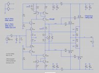
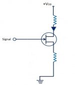
@woody, no, it's just poorly drawn because I never cleaned it up after playing with a few different ideas. The resistors are in parallel.
(I've also discovered that I can't find any metal films in 4W either, so they need doubling up again -- at which point there's not much point in showing them that way in SPICE.)
Here's a clearer version:
(I've also discovered that I can't find any metal films in 4W either, so they need doubling up again -- at which point there's not much point in showing them that way in SPICE.)
Here's a clearer version:
Attachments
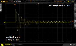
Consider the Hantek CC65 from eBay. I have one and I am pleased with the results I get from it.
I can certainly imagine other instances where being able to view the waveform would be very useful (such as determining the class A envelope -- assuming the output devices are on flying leads).
I did some Googling and Pico also sells one[1]. Looks like it was made in the same factory, but with slightly higher-spec parts (at least there's a strain relief on the cable, and a metal latch ring on the BNC). A bit more dosh, but maybe better quality control too?
Thanks for the idea, Mark!
Cheers,
Jeff.
[1] https://ie.farnell.com/pico-technology/ta018/current-probe-clamp-60a-oscilloscope/dp/2677035
To do it based on voltage drop across Q11 wouldn't you need to know what the transfer curve looked like at the rail voltage? (The datasheet only contains curves at 10Vds.)
- Home
- Amplifiers
- Pass Labs
- How do you measure bias with no source resistors?