In odd order enclosures like a 5th order bandpass where one side of the driver is fired directly into a port how do you calculate tuning on this?
I've designed standard 4th/6h order bandpass enclosures and standard T-lines but im just recently getting into horn enclosures. And with these compound horns I don't understand how you come up with the tuning for the lines, vents, horn sections, ports whatever you want to call them that aren't associated with a chamber.
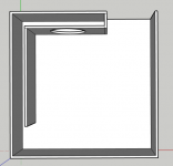
made a quick sketch to explain what I mean
I've designed standard 4th/6h order bandpass enclosures and standard T-lines but im just recently getting into horn enclosures. And with these compound horns I don't understand how you come up with the tuning for the lines, vents, horn sections, ports whatever you want to call them that aren't associated with a chamber.
made a quick sketch to explain what I mean
Attachments
What is a 5th order bandpass? How can it have an odd order?
Look at my sketch see how it fires directly into the vent in the top left corner which comes back into the shared chamber? This creates an odd order because it has no chamber added unlike a standard series 6th order.
Many odd order enclosure types exist. A Tline for example is a 3rd order enclosure
Never heard of this odd order in 30 years. Interesting where this might go.
I suppose if a t line had an acoustical slope half way between 2nd and fourth order boxes thats what one might call it??
I suppose if a t line had an acoustical slope half way between 2nd and fourth order boxes thats what one might call it??
Last edited:
It's technically 6th order, i.e. visualize it as a funky way to fold an inverse tapered, tapped T-TQWT.
GM
GM
It's technically 6th order, i.e. visualize it as a funky way to fold an inverse tapered, tapped T-TQWT.
GM
Idk the top chamber doesn't add a reactive order though, The only other person I could find talking about odd orders was PWK and he actually shows a nearly identical 5th order bandpass in this video.
He shows the enclosure in this video @ 2:20
YouTube
At what frequency is this supposed to have transmission line effects? When I look at the drawing I see a mass loaded speaker playing to itself in a box with a hole in it.
Technically, the big volume part is an enclosure with a helmholtz resonator. The open gap in the enclosure is the ports surface, the thickness of the L-shaped tunnel wall towards the opening is the port depth.
The L-shaped tunnel is a bit more complex. It's a resonant tube but can be seen as a compression chamber too. How it interacts with each other depends on the dimensions.
The L-shaped tunnel is a bit more complex. It's a resonant tube but can be seen as a compression chamber too. How it interacts with each other depends on the dimensions.

Not far from my 6th order mixed Helmholtz and quarter wave resonator HROAR bandpass design.
ROAR with Helmholtz front resonator
More info, simulations and measurements.
View attachment 761509
Not far from my 6th order mixed Helmholtz and quarter wave resonator HROAR bandpass design.
That's all but a good design. For starters, you can't get the driver out again. I doubt it will be linear either.
At what frequency is this supposed to have transmission line effects? When I look at the drawing I see a mass loaded speaker playing to itself in a box with a hole in it.
It's not nothing about it was tuned and all just a visual representation of adding an odd order. A 6th order series bandpass without the extra chamber. The outside port would be in the right of the driver
A 6th order series bandpass without the extra chamber
A chamber with a port is interchangeable with a quarter wave pipe section. Both will create a 6th order bandpass. A tapped horn does not have any chambers or ports but is quarter wave resonator based 6th order series tuned bandpass.

I doubt it will be linear either
If you with "linear" mean a smooth spl graph then here is the measured response of the HROAR10.

the driver is fired directly into a port how do you calculate tuning on this?
And to answer your original question how to simulate something like your posted example in the first post.
Since there are no measurements in your posted example I used a 736 x 736 x 436 mm (outer dimensions) box built out of 18 mm plywood, with a B&C 12PS100 driver. I tried to eyeball it to look quite similar to your design.
In the posted Hornresp simulation above I calculated the first quarter wave section to 95 cm length (LP2).
The large frontchamber is 151,16 liters (VC1).
The mouth/exit port is 800 cm2 cross section (Ap1) and 13,6 cm long (Lp1).
I hope this helps you with simulating your intended design.
Cheers,
Johannes

My simple sketch used in the first example.


A Hornresp simulation of what happens if you make the quarter wave pipe longer and the front chamber smaller (red curve).
I posted an updated sketch to show what I mean.
Cheers,
Johannes
- Status
- Not open for further replies.
- Home
- Loudspeakers
- Subwoofers
- How do you calculate tuning on a port without a chamber?