Yeah, I get that damping factor is useless and it's really a matter of output impedance. If I understand correctly, output impedance of an amplifier varies with frequency?
So that would mean that it would affect the frequency response of the amp right?
I'm wondering how you would do an impedance sweep of an amplifier's output. Does anyone know the standard test that determines an amp's DF at a given frequency? Or do these companies just make up numbers?
So that would mean that it would affect the frequency response of the amp right?
I'm wondering how you would do an impedance sweep of an amplifier's output. Does anyone know the standard test that determines an amp's DF at a given frequency? Or do these companies just make up numbers?
Well if you look it up you'll see damping factor is the ratio of the load impedance to the amplifiers output impedance.
So a rough and ready way to estimate... if you set the amp to give (say) 10 volts rms output (with no speakers attached) as measured on a DVM (use something like 400Hz which any DVM should cope with), and then load the amp with a known resistance as a load (say an 8 ohm or 10 ohm resistor of suitable rating) you will see the 10 volts drop a little as measured at the speaker terminals.
If we assume the amp internally is "perfect" as a voltage source then you can work out the damping factor. For example if you measured 10 volts and connecting a 10 ohm gave 9.8 volts then the internal resistance within the amp is dropping 0.2 volts.
The perfect amp is delivering current I of 10/10 (I=V/R) which is 1 amp. The internal resistance is R=V/I which is 0.2/1 = 0.2 ohm. So the ratio 0.2 to 10 is 50 which would be the damping factor.
That is a bit simplistic and there are other ways to measure damping factor more accurately and over a wider frequency range but if you only have a DVM it will get you in the right ballpark 🙂
Try the same test at the end of the speaker leads too such that they are in circuit as well and their resistance is included. Now that amplifier with a claimed 500 damping factor isn't so much different to one of only 30 or 40.
"tug-of-war" with a resistor load, another amp on the other end driven with your test signal
such as a frequency sweep
measure the V a your amp's output
a soundcard is good down to its crosstalk limit for such a test
such as a frequency sweep
measure the V a your amp's output
a soundcard is good down to its crosstalk limit for such a test
Well if you look it up you'll see damping factor is the ratio of the load impedance to the amplifiers output impedance.
So a rough and ready way to estimate... if you set the amp to give (say) 10 volts rms output (with no speakers attached) as measured on a DVM (use something like 400Hz which any DVM should cope with), and then load the amp with a known resistance as a load (say an 8 ohm or 10 ohm resistor of suitable rating) you will see the 10 volts drop a little as measured at the speaker terminals.
If we assume the amp internally is "perfect" as a voltage source then you can work out the damping factor. For example if you measured 10 volts and connecting a 10 ohm gave 9.8 volts then the internal resistance within the amp is dropping 0.2 volts.
The perfect amp is delivering current I of 10/10 (I=V/R) which is 1 amp. The internal resistance is R=V/I which is 0.2/1 = 0.2 ohm. So the ratio 0.2 to 10 is 50 which would be the damping factor.
That is a bit simplistic and there are other ways to measure damping factor more accurately and over a wider frequency range but if you only have a DVM it will get you in the right ballpark 🙂
Try the same test at the end of the speaker leads too such that they are in circuit as well and their resistance is included. Now that amplifier with a claimed 500 damping factor isn't so much different to one of only 30 or 40.
Thats a good way of testing amps' damping, i usually use this method but shredhead please keep in mind that the longer the cables wich you use to connect resistor to amp, the more wrong damping value you get , and also to decrease the cable's resistance use tick cable as posible as you can.
Last edited:
For example if you measured 10 volts and connecting a 10 ohm gave 9.8 volts then the internal resistance within the amp is dropping 0.2 volts.
The perfect amp is delivering current I of 10/10 (I=V/R) which is 1 amp. The internal resistance is R=V/I which is 0.2/1 = 0.2 ohm. So the ratio 0.2 to 10 is 50 which would be the damping factor.
Mooly, agree with most of your post but not on this. If the voltage drops to 9.8V with a 10 ohms load the Iout is not 1A but 0.98A...
Just to split some hairs 😉
Jan
Mea culpa 😀 The train of thought wandered while typing and wielding Windows on screen calculator.
Thanks 🙂
Thanks 🙂
That's how you do it in theory and practice:
Note that you can basically do this with two channels of one stereo amplifier as well, i.e. the resistor goes between R+ and L+, with playback on L and measurement on R. The resistor should be >10x the expected output impedance (current source approximation), but that shouldn't be an issue since you need something in the usual loudspeaker impedance range anyway. Sufficient load handling advised, shouldn't need to be anything too extreme though."tug-of-war" with a resistor load, another amp on the other end driven with your test signal
such as a frequency sweep
measure the V a your amp's output
I want to test a new amp and an old one to see the differences in the 20-40Hz area but for the old one I'm scared that because it doesn't really have much in the area of protection circuits, it might release the magic smoke.
Does anyone here have any experience in doing these 2 kinds of tests to an old quasi-complimentary dinosaur? Would one test be safer than the other?
Does anyone here have any experience in doing these 2 kinds of tests to an old quasi-complimentary dinosaur? Would one test be safer than the other?
Just do the test at a couple of volts and then there is no danger of anything overheating.
If you add a low value resistor (say 0.1 to 0.47) in series with the speakers then you automatically decrease damping factor down to at least 80 with a 0.1 ohm, and to just 17 with a 0.47 ohm. That assumes 8 ohm speakers and a perfect amplifier with a damping factor of zillions.
Try it.
If you add a low value resistor (say 0.1 to 0.47) in series with the speakers then you automatically decrease damping factor down to at least 80 with a 0.1 ohm, and to just 17 with a 0.47 ohm. That assumes 8 ohm speakers and a perfect amplifier with a damping factor of zillions.
Try it.
There is no chance getting a good measurement with an multimeter in the range of 400Hz and up to 20k or 40kHz.
This is an area only for modern Oscilloscopes
This is an area only for modern Oscilloscopes
Any meter should cover 400Hz. Its just a ballpark figure I think the OP is after rather than a detailed damping vs frequency sweep.
There is no chance getting a good measurement with an multimeter in the range of 400Hz and up to 20k or 40kHz.
This is an area only for modern Oscilloscopes
Thats right when i tried to measure some of well known brand amplifier every time i mesure the damping under amplifier's spesifications.
Nevertheless doing same test with two amplifier shows the differences between them even if the results are wrong, i think this is what exactly shredhead wants.
shredhead when you attach 10ohm aluminium resistor ( lets say 50w ) there would be no harm to the both of your amp, jut be careful to not short circuit the cables 🙂 do not take the result as they are true , because of the reason Kiriakos explaned well above.
I have described a method for using a DMM set to AC voltmeter that gives very accurate comparisons of voltage upto 50kHz.There is no chance getting a good measurement with an multimeter in the range of 400Hz and up to 20k or 40kHz.
This is an area only for modern Oscilloscopes
I know my poorest DMM does not work accurately at much away from 100Hz, but as a "comparative tool" it is superb, to it's 1 in 2000 count ability/resolution.
Any meter should cover 400Hz. Its just a ballpark figure I think the OP is after rather than a detailed damping vs frequency sweep.
This sounds more like a wish 🙂
Today you may say with 100% certainty that a multimeter is capable for volt measurements up to 600 Hz as soon you see on it an Low Pass filter selection.
There is an electrical application named as Variable frequency drives, that is motors operating with controllers capable to vary AC voltage frequencies in the range of 100 ~ 400 Hz, anything above 400Hz it needs to be suppressed (filtering of unwanted harmonics), and the Low Pass filter comes in to play as soon it gets activated ( so the measurement to include only energy that one motor can actually use).
In simple English, there is high bandwidth multimeter as desktop, but most people do not have them.
In portable multimeter some modern industrial ones are able for this 100~400Hz with good accuracy, but they are in the range of 200-400 USD.
As far I am aware regarding sound, all equipment and even speakers are tested in 1kHz, this automatically translates that the measurements instrument which did the measurement, it should be capable having five times more bandwidth as peak limit.
Naturally you may conduct measurements by having at hand one of the better handheld multimeter, but you always need to check their specifications datasheet so to manually correct the accuracy by recalculating the error due bandwidth limitations.
Regarding Oscilloscopes, their are not restricted in bandwidth, and therefore you may accept unquestionably their measurement by also accepting that even the most well made Oscilloscopes of our times (retail value 1000~3000 USD) comes with an accuracy of 2~3%.
In conclusion what it would bother someone who takes measurements seriously is the phrase as: Quality of measurement.
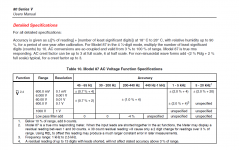
For example this is the specifications table of one super accurate multimeter.
45 Hz to 65 Hz / 0.7% + 20
65 Hz to 1 kHz / 1.0% + 25
1 kHz to 5 kHz / 2.0% + 25
5 kHz to 20 kHz / 2.0% + 40
What we should understand is that even the best in accuracy multimeter when measuring high bandwidth, it accuracy drop down and come close to an Oscilloscope which has this inferior 2~3% accuracy.
Now feel free to assume that every measurement that you see printed as specification, comes with 2~3% of accuracy, except if the manufacturer owns 50000 to 100000 USD Oscilloscope which has better accuracy. 😉
To the OP: measure if you wish, but be certain that in any of your amps damping factor will be quite high and in practice whatever the connecting wires let it be.
Doubt you will here any difference between 50 and 500 DF if the connecting wires have, say, 0.1 ohms resistance (or worse).
Use:
Cirris Systems - Wire Resistance Calculator & Table
Remember to use double the amp to speaker distance because both wires are in series.
Doubt you will here any difference between 50 and 500 DF if the connecting wires have, say, 0.1 ohms resistance (or worse).
Use:
Cirris Systems - Wire Resistance Calculator & Table
Remember to use double the amp to speaker distance because both wires are in series.
This sounds more like a wish 🙂
I'd still stand by what I say 🙂 that any meter will read 400Hz as well as 50 or 60Hz to within an acceptable deviation between the two frequencies. Whether its particularly accurate doesn't really matter as its just used to determine the relative drop of loaded vs unloaded. And a sine wave must be used at all times.
If you want more more accurate results you need more accurate gear and methodology... goes without saying... but for a rough and ready test... get measuring 😀
I will be using a Fluke 87-V if that helps. Here is the spec sheet on AC sine waves. Like I said, I'm mainly focused on the low end, 10Hz to 80Hz at the most.
The whole reason I am curious about this is because these two amps sound very different from each other when used as subwoofer amps. Their frequency response is pretty much dead on with each other with a non inductive load so I was thinking maybe what I'm hearing is something to do with DF.
The whole reason I am curious about this is because these two amps sound very different from each other when used as subwoofer amps. Their frequency response is pretty much dead on with each other with a non inductive load so I was thinking maybe what I'm hearing is something to do with DF.
Attachments
The whole reason I am curious about this is because these two amps sound very different from each other when used as subwoofer amps. Their frequency response is pretty much dead on with each other with a non inductive load so I was thinking maybe what I'm hearing is something to do with DF.
More likely, the bass difference has to do with the power supply bulk capacitance, or maybe the coupling capacitors, if any, in the amps.
I will be using a Fluke 87-V if that helps.
This is old and slow at measuring anything as 1mV AC up to 150mV AC.
But as long you are measuring in the volts range you are good to go.
More likely, the bass difference has to do with the power supply bulk capacitance, or maybe the coupling capacitors, if any, in the amps.
I don't think it's that. I'm not pushing these amps anywhere near their PSU limits and they have the same rolloffs down low so I don't think it is a coupling cap thing.
Thanks for the tip Kiriakos, I will keep that in mind.
- Status
- Not open for further replies.
- Home
- Amplifiers
- Solid State
- How do I test an amp for Damping Factor?