In particular, this circuit:

If I inject my AC1 source at the input then of course all my gain is negative, and there's no zero-crossing at which to measure the phase margin.
If I inject AC1 at the output and measure the gain also at the output, then I do get a zero-crossing, but it's long and flat, and I'm not sure it's the right thing to be measuring.

What's the correct way to do this?
Thanks,
Jeff.
If I inject my AC1 source at the input then of course all my gain is negative, and there's no zero-crossing at which to measure the phase margin.
If I inject AC1 at the output and measure the gain also at the output, then I do get a zero-crossing, but it's long and flat, and I'm not sure it's the right thing to be measuring.
What's the correct way to do this?
Thanks,
Jeff.
for conventional stability analysis, inject a small AC signal into the error amplifier -- i.e. break the loop to Q6 base with a small signal source.
the phase margin is unaffected by the DC input. Simply use a DC source and skip the rectifiers and caps. Always simplify when starting out in SPICE, you can complexify later.
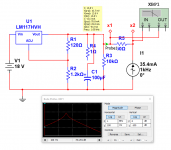
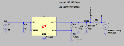
Another method, the socalled "non-invasive" method injects an AC current source onto the output, 25mA or less. Then perform the AC Transfer analysis. LTSpice gives you Tg. From Tg you can derive stability. that is, the change of output impedance wrt frequency of a regulator tells you all you need to know about stability.
Take one of the stock Linear Tech/Analog Devices canned files for one of their low drop out regulators and play around with them.
the phase margin is unaffected by the DC input. Simply use a DC source and skip the rectifiers and caps. Always simplify when starting out in SPICE, you can complexify later.
Another method, the socalled "non-invasive" method injects an AC current source onto the output, 25mA or less. Then perform the AC Transfer analysis. LTSpice gives you Tg. From Tg you can derive stability. that is, the change of output impedance wrt frequency of a regulator tells you all you need to know about stability.
Take one of the stock Linear Tech/Analog Devices canned files for one of their low drop out regulators and play around with them.
Last edited:
While I was studying for a Bachelor of Science in EE, it took me three full years to figure out how to even approach these kinds of analyses. Hats off to everyone / anyone who "gets it" after reading a chapter in a book purchased from Amazon! You're a faster study than me, that's for sure.
Sometimes I think to myself that "simplification authors" do their readers a huge disservice. I think to myself, there are SOME topics that can't be glibly explained by ridiculously simplistic approximations / analogies. Perhaps instability of control systems may be one such topic. Or, maybe I am dumb. Could be either one.
Sometimes I think to myself that "simplification authors" do their readers a huge disservice. I think to myself, there are SOME topics that can't be glibly explained by ridiculously simplistic approximations / analogies. Perhaps instability of control systems may be one such topic. Or, maybe I am dumb. Could be either one.
See PERFORMANCE MEASUREMENTS
Page 109; CV Load Effect Transient Recovery Time (Load Transient Recovery)
http://literature.cdn.keysight.com/litweb/pdf/5952-4020.pdf
Poor phase margin will produce several cycles of ringing. Good phase margin will produce no ringing.
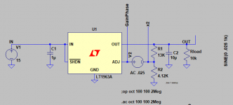
Operate the regulator as an amplifier: inject a sine wave at the base of Q5 and add an output resistor (remove C8 and C11). Measure phase shift at the base of Q5 and the output resistor at unity gain.
Page 109; CV Load Effect Transient Recovery Time (Load Transient Recovery)
http://literature.cdn.keysight.com/litweb/pdf/5952-4020.pdf
Poor phase margin will produce several cycles of ringing. Good phase margin will produce no ringing.
Operate the regulator as an amplifier: inject a sine wave at the base of Q5 and add an output resistor (remove C8 and C11). Measure phase shift at the base of Q5 and the output resistor at unity gain.
Last edited:
for conventional stability analysis, inject a small AC signal into the error amplifier -- i.e. break the loop to Q6 base with a small signal source.
the phase margin is unaffected by the DC input. Simply use a DC source and skip the rectifiers and caps. Always simplify when starting out in SPICE, you can complexify later....
D'oh. I had tried breaking the loop at the inverted input, but of course with the AC source still there it floods the small signal. Once I removed the AC input, rectifiers and caps, it works fine.
I'm going to try and get my head around some of the other suggestions as well. Just wanted to confirm a positive result.

While I was studying for a Bachelor of Science in EE, it took me three full years to figure out how to even approach these kinds of analyses. Hats off to everyone / anyone who "gets it" after reading a chapter in a book purchased from Amazon! You're a faster study than me, that's for sure.
You should've studied harder.
") I got a "D" in organic, now own a specialty chemical company. Go figger.
I got a "D" in organic, now own a specialty chemical company. Go figger.The non-invasive method and method breaking the loop are described in this application note from Omicron-Lab. If you need to get into the math there are citations.
https://www.omicron-lab.com/fileadm...ote_TraditionalNoninvasive_Stability_V1_3.pdf
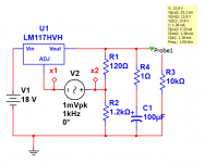
Some pix -- from Multisim -- a little easier than LTSpice since you don't have to rewrite the equations with their (Multisim) virtual instruments.
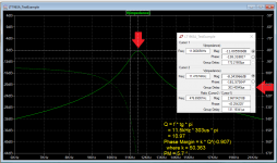
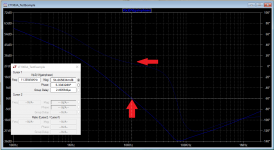
Gain/Phase Method, Impedance Method -- a 100uF cap with no ESR is used to illustrate the instability.
Gain/Phase Method, Impedance Method -- a 100uF cap with no ESR is used to illustrate the instability.
Attachments
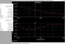
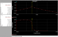
Since LTSpice gives you Group Delay, you can calculate the phase margin from a couple of equations, you can do it by analyzing gain/phase or impedance --
Attachments
Last edited:
Many solid state loads provide a function to test load transient response.

This is how to test power supply performance.
Using the fast dynamic load described in this Design Idea to test the transient response of a power system can reveal many critical operating characteristics. The voltage deviation resulting from a fast current step can provide insight into a regulator’s phase margin (Reference 2).
https://www.edn.com/design/power-management/4438518/Transient-load-gives-power-systems-a-workout
Make the input with two adjustable voltages and a FET switch to alternate between them for two different load currents.
This is how to test power supply performance.
Using the fast dynamic load described in this Design Idea to test the transient response of a power system can reveal many critical operating characteristics. The voltage deviation resulting from a fast current step can provide insight into a regulator’s phase margin (Reference 2).
https://www.edn.com/design/power-management/4438518/Transient-load-gives-power-systems-a-workout
An externally hosted image should be here but it was not working when we last tested it.
Make the input with two adjustable voltages and a FET switch to alternate between them for two different load currents.
Last edited:
Many solid state loads provide a function to test load transient response.
This is how to test power supply performance.
I know the chairman of TDI -- went to the same grad school w me!
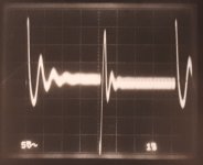
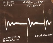
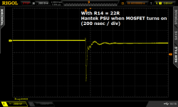
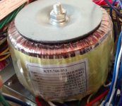
Figures 1 and 2 below show the load transient response of a linear power supply, Hantek model PPS2320A (specs and user manual) . . . photo of its power transformer courtesy of EEVblog, figure 3 below.
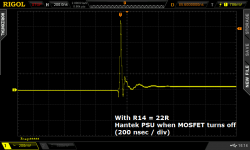
In these tests, power supply output voltage was set to 12.5V. Load current is switched between 0.5A and 1.0A with a risetime / falltime of 50 nanoseconds. I have no idea why EDN magazine author Mike Rose, or Hewlett Packard's manual authors, think that 1000 nanoseconds is a good choice for risetime / falltime. In my opinion, zero is the best choice, and as-low-as-possible is the second best. (BTW "R14" in the figure captions refers to the tuning component which sets the rise and fall time of the load transient tester.)
During a load transient in which load current steps down in 50 nsec (figure 1), the Hantek supply's output voltage spikes upward by 900 mV and there is a tiny amount of ringing which completely dies out within 600 nanoseconds.
During the other type of load transient, in which load current steps up in 50 nsec (figure 2), the Hantek's output voltage spikes downward by 700 mV and again there is a tiny amount of ringing, which completely dies out within 600 nanoseconds.
Using a load transient tester whose risetime and falltime is 1000 nanoseconds, would prevent these spikes from occurring at all. Setting the oscilloscope horizontal sweep rate to 1 million nanoseconds per division, as in post #11, would obscure the measurement yet further.
Pictures copies from this old diyAudio thread: link
Attachments
- Status
- This old topic is closed. If you want to reopen this topic, contact a moderator using the "Report Post" button.
- Home
- Amplifiers
- Power Supplies
- How do I measure the phase margins of a regulator?