...how do I measure the amperage of the 3.3v/5v/12v 24 pin ATX mobo input please?
I have a UNI-T UT71B DMM.
Please be patient as I have learning difficulties and sometimes absorb information in unusual ways!
Many thanks!
Cheers!
I have a UNI-T UT71B DMM.
Please be patient as I have learning difficulties and sometimes absorb information in unusual ways!
Many thanks!
Cheers!
The easiest way is to use a DC Clamp meter and measure the current flow of each individual wire feeding your mother board. Tease the wires loose and place the clamp meter around individual wires. Otherwise you must break the loom and place your meter in DC current mode in series with each feed, messy!
The easiest way is to use a DC Clamp meter and measure the current flow of each individual wire feeding your mother board. Tease the wires loose and place the clamp meter around individual wires.
Otherwise you must break the loom and place your meter in DC current mode in series with each feed, messy!
I tried 2 different clamp meters as stated by you here. Unfortunately the readings were very low. I of course did sum all the 5v wires together to get a total current draw; same with the 3.3v, 12v. e.g. just a few mV each! Didn't seem accurate to me?
As for the DMM "break loom" method, I was told this: "Most ATX connectors are running a number of duplicates of each voltage because otherwise the 18AWG wires used are not heavy enough for the current carried. In other words, several 12V lines are joined together at the motherboard end. So when you cut one wire to put your meter in series, the land mostly just shifts to the remaining wires where there is less resistance (than the meter) to pass through, that is why this method does not work….." ...Do you concur with this explanation or is it untrue?
Many thanks!
MY HTPC:
MSI Z370i GAMING PRO CARBON AC mini-ITX + Intel® HD Integrated Graphics 630.
Intel Core i7 Coffee Lake 8700 SE Gen.8 2.9GHz LGA1151 TDP 35W CPU.
Pink Faun i2s Bridge PCI-e (expansion/riser) Card.
Samsung (250GB) 960 M.2 (2280) Evo PCIe 3.0 (x4) NVMe 3D V-NAND SSD MZ-V6E250BW (x1).
Patriot Viper 4 16GB Dual Ch. DDR4 3000MHz PC4-24000 DIMM PV416G300C6K.
Streacom st-fc9b-alpha PC Fanless Chassis.
Seasonic Prime Ultra ’80+’ Titanium 650 Watt ATX M-PSU.
a few mV implies you're measuring voltage, not current. And the above about parallel runs is completely true. You can get an ATX extenion cable and use that as a way to make a shunt feed without ruining the wiring on your ATX.
a few mV implies you're measuring voltage, not current. And the above about parallel runs is completely true. You can get an ATX extenion cable and use that as a way to make a shunt feed without ruining the wiring on your ATX.
Yes, sorry! ~ typo error! I meant mA (milliamps) i.e I was set to DCA.
I already got an extension so I wouldn't have to 'butcher' the real cable.
Please explain more about the shunt feed? What is it, how do I make it, many thanks!
What exactly you want to measure? Power consumed by your PC or maybe power supply capabilities? Properly measuring ATX power supply is a rather complicated task. Cheap DMM is not sufficient. If you want to do it properly you need special hardware. Test methodology of ATX PSUs is explained well in this article - Hardware Secrets Power Supply Test Methodology - Hardware Secrets
What exactly you want to measure? Power consumed by your PC or maybe power supply capabilities? Properly measuring ATX power supply is a rather complicated task. Cheap DMM is not sufficient. If you want to do it properly you need special hardware. Test methodology of ATX PSUs is explained well in this article - Hardware Secrets Power Supply Test Methodology - Hardware Secrets
A professional LPSU designer and builder has asked me to supply the amperage/current/load for the 3 rails that feed my mobo (listed above), 3.3, 5, 12v. This is so he can custom make a LPSU tailored to my needs. So, I need to measure the current draw of the mobo, not what the PSU supplies. I don't think the builder realised my limited skill/knowledge level! He simply asked me to measure the 'voltage drop' across a resistor? (using a meter). Maybe like this:
Attachments

Last edited:
Properly measuring ATX power supply is a rather complicated task. Cheap DMM is not sufficient.
So, do you agree with the first reply that a clamp meter is sufficient?
Cheers!
The easiest way is to use a DC Clamp meter and measure the current flow of each individual wire feeding your mother board. Tease the wires loose and place the clamp meter around individual wires. Otherwise you must break the loom and place your meter in DC current mode in series with each feed, messy!
Is it best to select: Amps or milliamps for this task (if there are choices available on a dial i.e. not auto-select)?
Cheers!
Well, I don't want to start offtopic but linear power supply for PC is a complete waste of money. It won't improve sound quality as some may admit. There are lots of switchers on the motherboard and every component anyway. Your Seasonic PSU is completely fine, high-end unit and it probably would provide much cleaner power than most linear PSUs.
Measuring current on every lane would be really hard and will differ widely with load (components draw a lot more current during stress rather than in idle). Especially if you are not experienced, there are big chances you will damage something when trying to measure with shunt. Imho its better idea to estimate it from components.
Measuring current on every lane would be really hard and will differ widely with load (components draw a lot more current during stress rather than in idle). Especially if you are not experienced, there are big chances you will damage something when trying to measure with shunt. Imho its better idea to estimate it from components.
Well, I don't want to start offtopic but linear power supply for PC is a complete waste of money. It won't improve sound quality as some may admit. There are lots of switchers on the motherboard and every component anyway. Your Seasonic PSU is completely fine, high-end unit and it probably would provide much cleaner power than most linear PSUs.
Measuring current on every lane would be really hard and will differ widely with load (components draw a lot more current during stress rather than in idle). Especially if you are not experienced, there are big chances you will damage something when trying to measure with shunt. Imho its better idea to estimate it from components.
Yes, heard this many times in many ways:
“Most, if not all, commercial motherboards contain extremely noisy DC to DC converters and switch mode regulators. Thus, even though an expensive linear power supply may be used on the outside, the power signal is going through a gauntlet of garbage once it hits the motherboard on its way to the output that feeds power to a USB DAC. It's like running a linear supply though a terrible switching supply in order to feed a DAC”.
However, TeraDak & HDPlex make LPSU’s for ATX PC’s ~ Why?
My Seasonic is a 10mA ripple SMPS but as such, must generate the switching parasitic noise and also feed this backwards into other devices and the mains. True it is one of the best available at the moment though! The probability of it being cleaner than branded LPSU’s is pure conjecture IMO.
Yes, I know that the current drawn varies at: boot-up/idle and in use (playing FLAC’s etc.) That is why I was asked to produce a measurement for all of those scenarios (i.e. boot/idle/in use), and do each measurement several times to ensure reasonable accuracy.
Unfortunately, the builder won’t accept estimates based on components alone, I wish that were so! (LOL). No, he wants actual measurements/readings.
Thank you for your concern, but I don’t think I would damage anything if I was shown the correct procedure in using a shunt, and after all the on topic question was: “how do I measure amperage”.
Your post doesn’t really address that issue with a qualified answer; you have mainly asked me questions rather than provide an answer to the OP.
It doesn’t matter that you were starting off-topic, that’s OK! (LOL).
Many Thanks.
Take Care.
Still waiting for the shunt procedure, for an ATX 24 pin mobo input current measurement.
Thanks in advance!

Thanks in advance!
Why? Because they earn money on this 🙂 Properly designed SMPS won't introduce any noise to load or mains. Otherwise, it won't pass EMI/EMC safety marks. Our fellow diyaudio member is achieving -130dB THD with Meanwell SMPS in headphone amplifier so I bet you don't really need anything fancier to much less sensitive device like PC.
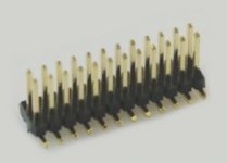
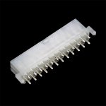
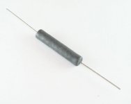
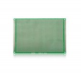
Anyway, if you really still want to measure that current you would need male and female 24 pin ATX connector, few 0.1 Ohm 5-10W. Solder it on universal PCB, place resistor in series with 3.3V / 5V / 12V lane. Measure voltage at each resistor. From Ohms Law I=U/R so for eg. I = 0.75V / 0.1 = 7.5 amps. Be careful to not short anything as you may end with fried PC. Keep in mind that under high load under voltage protection may kick in considering voltage drop at shunt. I don't think you will get any meaningful results with clamp meters.
Anyway, if you really still want to measure that current you would need male and female 24 pin ATX connector, few 0.1 Ohm 5-10W. Solder it on universal PCB, place resistor in series with 3.3V / 5V / 12V lane. Measure voltage at each resistor. From Ohms Law I=U/R so for eg. I = 0.75V / 0.1 = 7.5 amps. Be careful to not short anything as you may end with fried PC. Keep in mind that under high load under voltage protection may kick in considering voltage drop at shunt. I don't think you will get any meaningful results with clamp meters.
Why? Because they earn money on this 🙂 Properly designed SMPS won't introduce any noise to load or mains. Otherwise, it won't pass EMI/EMC safety marks. Our fellow diyaudio member is achieving -130dB THD with Meanwell SMPS in headphone amplifier so I bet you don't really need anything fancier to much less sensitive device like PC.
Anyway, if you really still want to measure that current you would need male and female 24 pin ATX connector, few 0.1 Ohm 5-10W. Solder it on universal PCB, place resistor in series with 3.3V / 5V / 12V lane. Measure voltage at each resistor. From Ohms Law I=U/R so for eg. I = 0.75V / 0.1 = 7.5 amps. Be careful to not short anything as you may end with fried PC. Keep in mind that under high load under voltage protection may kick in considering voltage drop at shunt. I don't think you will get any meaningful results with clamp meters.
Thanks for your reply! I am not entirely clear on this though(?):
"you would need male and female 24 pin ATX connector, few 0.1 Ohm 5-10W. Solder it on universal PCB"...
Can you elaborate any further? Picture? drawing?
Cheers!
"you would need male and female 24 pin ATX connector, few 0.1 Ohm 5-10W. Solder it on universal PCB"....
you mean these:
you mean these:
Attachments
- Status
- Not open for further replies.
- Home
- Amplifiers
- Power Supplies
- how do I measure the amperage of the 3.3v/5v/12v 24 pin ATX mobo input?