May be this is a silly question, but forgive me, as I am a tube guy: How do I match bipolar transistors like the MJ15003 (for building the JLH)?
Thanks
Thanks
Start by looking at this thread:
http://www.diyaudio.com/forums/showthread.php?s=&threadid=16518&highlight=matching
http://www.diyaudio.com/forums/showthread.php?s=&threadid=16518&highlight=matching
THX, but
..this threat is only talking about how difficult it is to match, not really what the practical setup is and how you come to a result. Mosfet-matching I learned by the Aleph-X-threat, but bipolars ?
..this threat is only talking about how difficult it is to match, not really what the practical setup is and how you come to a result. Mosfet-matching I learned by the Aleph-X-threat, but bipolars ?
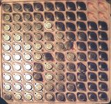

I love Bananas!
Olala!
Nice pics! You can build lots of amps from that, yes? Wish I was your neighbor!
JojoD
Olala!
Nice pics! You can build lots of amps from that, yes? Wish I was your neighbor!
JojoD
What matching is needed?
Unless you feel the need to raise the B+ and parallel more outputs in the search for higher power no matching is needed.
Even if you did feel the need for the above, normal emitter resistors in the range of 0R22 would force current sharing.
Unless you feel the need to raise the B+ and parallel more outputs in the search for higher power no matching is needed.
Even if you did feel the need for the above, normal emitter resistors in the range of 0R22 would force current sharing.
Get them from me,
I've still got some matched pairs MJ15003 left from a tray similar as the picture in this thread.
They are matched for as close as possible hfe at Ic of 0.6 A and 0.9 A.
I've still got some matched pairs MJ15003 left from a tray similar as the picture in this thread.
They are matched for as close as possible hfe at Ic of 0.6 A and 0.9 A.
if you have PowerPoint
if you just need a tightly balanced differential amplifier, consider using the Intersil "long tail pairs" - I just made a high speed comparator using them (they are SMT, however.)
here's a good article from a couple guys at UTexas, Arlington:
http://www.uta.edu/ronc/4345sp02/lectures/L20_4345_Sp02.ppt
djk said:What matching is needed?
Unless you feel the need to raise the B+ and parallel more outputs in the search for higher power no matching is needed.
Even if you did feel the need for the above, normal emitter resistors in the range of 0R22 would force current sharing.
if you just need a tightly balanced differential amplifier, consider using the Intersil "long tail pairs" - I just made a high speed comparator using them (they are SMT, however.)
here's a good article from a couple guys at UTexas, Arlington:
http://www.uta.edu/ronc/4345sp02/lectures/L20_4345_Sp02.ppt
Honestly, I don't know how to do it but I repair Peavey and Crown amps and Crown matches their transistors in 2's, 4's, and 8's. They highly encourage it for their amps or maybe problems. I don't know if it is a design issue but I know when a Crown amp is built and set up properly, they are a real work-horse and perform very well and mostly they blow anly a couple outputs out of a string of 8 or more. Pretty impressive.... Old Peavey gear is the same. Rarely does it blow all outputs, only a couple or maybe 3. Peavey doesn't necessarily match their parts but they go through a strict screening process before Peavey will buy them so there is something to be said for screening and or matching. I'm sure that design has something to do with it.
Chris
Chris
I have a technique which works very well.
Output transistors should be matched on two parameters for best results, not just one.
The matching process should be done at the intended bias current the amp is to be set up to; in my amps I choose 58mA. The devices should be matched for current gain and base/emitter voltage.
I built a simple jig with a current source which supplies this current to the transistor under test. A differential pair senses a reference voltage of half the Vcc (I use a 12V gelcel battery), and adjusts the bias on the base of the device under test (DUT) to ensure half the Vcc between collector and emitter. There is a 100R resistor in series with the base of the DUT so I can measure the voltage drop across it, giving me the current through into the base and thus permitting the operator to figure the beta of the DUT.
Once stable, I first measure the base/emitter voltage of the DUT.
I go through a sample of 100 or so devices, and categorize them in small piles by Vbe on a large sheet of butchers paper. Remember, this is at a prescribed current with around 6V across the collector/emitter.
You need to work reasonably quickly (less than two seconds) to avoid warming the junction too much, as the gain and the Vbe rises rapidly with temperature.
A fast sampling rate on the DMM is essential. In a sample of 100, you will get an approximately normal distribution of Vbe, and these can be sorted right down to the nearest millivolt, very accurate since 1mV in 600mV is around 0.16%.
Once you have multiple piles, all classified by Vbe, you then go through each pile searching for betas within 5%. For this you move the DMM probes to the 100R base stopper. The higher the reading, the lower the beta, given by 5800 divided by mV. (58mV is a beta of 100).
In this way you finish up with matched pairs which will turn on and off together and which will pass pretty much identical collector currents as well. This pays dividends in the final sound, as switching noise is much reduced. Generally I can accurately matched 60% of a batch of 100 Toshiba 5200/1943s in about forty minutes. The accuracy depends, of course, on the quality of your DMM. Make sure the battery is good!
Cheers,
Hugh
AKSA said:
I built a simple jig with a current source which supplies this current to the transistor under test. A differential pair senses a reference voltage of half the Vcc (I use a 12V gelcel battery), and adjusts the bias on the base of the device under test (DUT) to ensure half the Vcc between collector and emitter. There is a 100R resistor in series with the base of the DUT so I can measure the voltage drop across it, giving me the current through into the base and thus permitting the operator to figure the beta of the DUT.
I have a couple jigs -- the require screwing down the transistor or MOSFET -- usually I will get a batch in and match a few hundred at a time.
When I am done I put the results in an Excel spreadsheet -- and generate a histogram -- which serves no useful purpose -- only for my amusement.
- Status
- Not open for further replies.
- Home
- Amplifiers
- Solid State
- How do I match bipolar transistors like MJ15003 ?