I have this adjustment with a resistance that I slide a metal ring with a wire attached to it,I have a little gauge that tells me approx. where there high frequencies it is leveled but seems not to play exactly the same on each side but they are on the same spot.any type of mesument I can do with a multimetre?and is ther a modification I can do to have a sort of exterieor adjustment like other 2+2?
Attachments
the only problem with that is I have to undo the back every time and it's quite long so if I can have a reading of some sort,it would help getting the right sound faster.
so if I can have a reading of some sort,it would help getting the right sound faster.Hi,
most important is that both chanels sound the same and in the same volume level. Because of building tolerances it can be possible that different polarizing Voltages are needed. Normally this voltage is set to an operating point where even considerable change of its level only results in a very small change in output volume level of the speaker itself.
If You want to measure the voltage at the output of the HV-generator You´ll need a HV-voltage probe. First a normal multimeter isn´t able to withstand several kV of votage and secondly is the inner resistance of the multimeter too low. The HV-generator can´t supply for such low loads and its output voltage drops. So You need something with an high enough inner resistance and voltage capability. That´s what an HV-probe supplies for. You might buy one for Your multimeter, or You may build one. I made mine from 100 series connected 10Megohm resistances, giving an overall resistance of 1Gohm (standard metal film).
When connected to the HV on one side and ground on the other You can measure the voltage over the last resistor (going to gnd). Normally Multimeters have an inner resistance of 10MegOhm. So the last resistor and the multimeter form a combined resistor of 5MegOhms. After the voltage-divider-rule the voltage over this resistance is Umes= UinputHV *(Rmes/R total). With Rmes = 5MegOhm and Rtotal=995Meg (without the multimeter Rtotal=1000MegOhm). From this You can calculate the unknown UinHV of the HV-Generator. UinHV=Umes(Rtotal/Rmes). In my case a 1V reading on the multimeter woud give 995V UinHV of the HV generator.
Thats not perfect and leaves room for quite big measuring failures, but at least You can have two identical readings and a rough idea whats going on.
jauu
Calvin
I think the simplest way to check is to use an SPL meter, run a noise track or FM interstation noise place the meter exactly at the same distance, like 1 foot centered on the middle panel exactly and see what the meter says.
Place the tweeter levels at minimum first (or disconnect)- this will give you base reference to see if the panels are both at the same basic levels.
If not, swap the interfaces - if the level imbalance shifts, probably you have a bad HV string in the multiplier.
Btw, that does not look like a 121 MkII interface...?
_-_-bear
I like the idea of the SPL meter. I used my measurement software to match both of my ESL to a fraction of a dB. No matter how carefully you build your stators and panels, there will be slight differences. If you design your HV supply to be adjustable, then you can tune out the differences. My panels were only slightly different (fraction of a dB), but my soundstage got much better when tuned.
Sheldon
Sheldon
a db meter sounds good,I will take a closer picture of the interface,but it.s a medallion,I 'll write the model tommorrow.
after 3 days of charging It sounds already better...
after 3 days of charging It sounds already better...

![IMGDEAD]](/community/proxy.php?image=http%3A%2F%2F%5BIMGDEAD%5Dhttps%3A%2F%2Fi69.photobucket.com%2Falbums%2Fi76%2FAUDIA8MAN%2FAUDIO%2520MAISON%2Faudiomaison040.jpg%5B%2FIMGDEAD%5D&hash=c5773ccb6b28884ac12a28be75818a99)
Ok, first thing - no matter what.
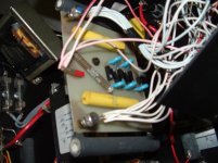
Get RID of that blue electrolytic cap that is in parallel to the yellow and silver (polystyrene) cap, I think in pic 2, that is in the audio path!! Replace with polypropylene of the same or similar value.
BIG difference!
Now, I can not see if you have two or one audio step up (drive) transformer in the the interface box or not??
The slider on the HF level control can be replaced with a LARGE like 20 watt or 50 watt rheostat, as is in the 121 MkII interface... but it is not necessary really. Or you could parallel a slightly smaller rheostat with the existing resistor, of course it would be a higher resistance unit... or add taps and put a switch in... 😀
how about a wide shot of the innards?
_-_-bear
Hmmm... my 121-Mk2A interfaces have a different physical package...
A wide shot top down, showing the overall layout would be excellent. But we can assume that they are essentially the same electrically.
So, definitely change out the electrolytic cap, ASAP.
On my unit the the resistor w/slider is a rheostat. No reason not to buy a pair and sub them in... gotta be similar wattage rating though. These are have fat wire and are ceramic... surplus would be least expensive probably... remember you can get away with a slightly smaller or larger value, since most of the time the thing is at a mid position... or do the shunt trick as I already suggested.
Probably yours has the 50 ufd coupling to the mid/hf xfrmr. It can be argued that the 200ufd coupling is better/worse depending on your ears, etc... all of the early models had the 200ufd coupling there... you could always split the diff.
Keep in mind that the xfmrs overlap function by a full 3 octaves or more!! It's not a crossover in the usual sense.
_-_-bear
An externally hosted image should be here but it was not working when we last tested it.
An externally hosted image should be here but it was not working when we last tested it.
An externally hosted image should be here but it was not working when we last tested it.
hope this helps thx for helping me upgrade,the electrical cord should be upgraded with the speaker connectors right?
what about the fuses
??
are those in the signal path?
could they be canceled?
oh and checked the ohms of the tweeter adjuster,and got 2.4 ohms on each perfect adjustment first shot😎
??
are those in the signal path?
could they be canceled?
oh and checked the ohms of the tweeter adjuster,and got 2.4 ohms on each perfect adjustment first shot😎
I am worrying about you, newfinish!
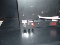
The fuse that is in the fuseholder that goes through the panel is in the signal path. Personally, I eliminate them, but that absolutely will put your xfmrs in a position to be fried. Otoh, it will eliminate a cheezy fuse that is non-linear.
The two fuses in the internal fuse holders are line fuses. Do NOT remove them.
To repeat: REPLACE the blue electrolytic cap that is in the upper left of the third picture you posted. Replace it with a film cap - preferably using polypropylenes - ASAP!!
That will make the single largest positive improvement in the overall sound that you can make.
_-_-bear
I have changed the electrolytic 47mf that you told me,my other question is which color wire really goes with the blue dot on the screw,is it the light blue wires or the white wires?I lost the othe rcolor on the other screw and want to make sure that the panels work in phase pushing before pulling,thx in advance so far so good didnt break anything yet!!
with everything recharged I should be able to give a good listening and feed back next saturday😀
with everything recharged I should be able to give a good listening and feed back next saturday😀
ummmm... same one as in the pictures you posted??
😀
Let us know what if any differences you hear from the cap change??
_-_-bear
😀
Let us know what if any differences you hear from the cap change??
_-_-bear
finally found the color of the wire on the board,had to flip it and its engraved on it.blue and white.😀
the cap is way bigger this one,a solen 250 volt ployprop.
![IMGDEAD]](/community/proxy.php?image=http%3A%2F%2F%5BIMGDEAD%5Dhttps%3A%2F%2Fi69.photobucket.com%2Falbums%2Fi76%2FAUDIA8MAN%2FAUDIO%2520MAISON%2Faudiomaison055.jpg%5B%2FIMGDEAD%5D&hash=fec1da462c34f48f2f049725c954d861)
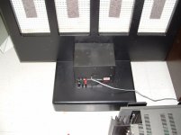
I just finished my rack unit.
the cap is way bigger this one,a solen 250 volt ployprop.
I just finished my rack unit.
NICE!!
Now you gotta damp that floor!!
(get a rug?)
And put some diffusion/absorption on the walls!!!
back wall too!!
😀
_-_-bear
Now you gotta damp that floor!!
(get a rug?)
And put some diffusion/absorption on the walls!!!
back wall too!!
😀
_-_-bear
thx well the rug was rolled away (in the right bottom picture)so has came back and i'm experimenting along the sides with sonopan 2 x2'x4' on each side. and in the back I'm puting the quilt I have,it did a great job alone so keep in touch thursday.cause tonight is hockey night with the canadians,good seated pair of tickets,can't miss that!!!!
- Status
- Not open for further replies.
- Home
- Loudspeakers
- Planars & Exotics
- how do i know if my hf on my acoustat 2+2 are the same level?