I bought a couple of these DACT Type SMD Stepped Attenuator 21 step *** Free ship *** ebay item number 190844814249 to make a dual volume control box for A/Bing amps. They work very well. I got a 50K model.
Member
Joined 2009
Paid Member
Even with the iPod cranked way up the speaker was very soft.
Is it normal that it didn't go very loud?
No it's not normal, there's something wrong - it should not be very soft, it should be pretty darn loud.
Put your DMM on 'ac' and measure the voltage at the output (no speaker) when you have it cranked up to it's loudest volume setting. The meter will give you a rough indication of the signal level and you should be able to measure several volts (e.g. 10V rms). A very soft sound means you likely have less than 1V of signal at the output which is not correct.
I assume you took the halogen lamp out of the circuit otherwise your power rails will sag under load.
You could have miswired the volume pot. Check here: ESP - A Better Volume Control
There are other possibilities of course - a photo of the completed amp showing wiring might help the other chaps on this forum offer further advice.
So yeah, I followed up on the tip to check all resistances, not just their values, but their locations in the circuit. And now I noticed that I had swapped a 22kR and a 220R resistor. So there was a 22k resistor on the input signal..
Now it works! loud music is coming from the amp. I don't hear any weird noises or static, so I think it's working pretty well 😀
Next step, the other channel!
After that it will be time to think about the case. I was thinking making it out of wood somehow, with 1 side having a thick aluminum panel. Would that be enough cooling, or do I really need something with fins?
Hey Tinco, Glad you're making music from one channel. I suggest that you try to get something with fins, like the Amp Camp Amp size (see the store). I built a stereo chip amp on an old 25WPC receiver's skimpy heat sinks and it sounded terrible at more than a whisper. Put it on a sink similar to ACA sink and now it sounds pretty good with both channels on the one sink. Why? I think that the thermal protection circuit was kicking in. The old sink had a very thin base and thin fins that looked like they had been pulled up with a peeler.
Simple way test if the single exposed side of aluminum would be good enough - build a cardboard enclosure and see if you hear the protection kicking in. I think you should try for something at least 3 mm thick. More is better as it allows heat to spread more easily.
Simple way test if the single exposed side of aluminum would be good enough - build a cardboard enclosure and see if you hear the protection kicking in. I think you should try for something at least 3 mm thick. More is better as it allows heat to spread more easily.
Agreed. Worst case, both channels driven to max. continuous output with 4R loads, you may need to dissipate up to 40W in heat. That's unlikely in normal use but it suggests a heatsink rating of 1 degC/watt or less. That's not huge or expensive but I think a 3mm sheet could still be a problem in the way BobEllis describes. To make attachment easy and run it cooler, you can always mount the chips to 2-3mm sheet and then attach external heatsinks using thermal transfer grease, immediately behind the chip(s). This is a local example of what might suit that approach: Altronics - H0580 125 x 75mm Extra Heavy Duty Heatsink
Using just a sheet heatsink at modest levels can work too but the whole panel gets warm. With a solid workout on heavy bass output, it means any other fittings like power socket, connectors and cables even, get a heat treatment. Probably not a wise move.
Using just a sheet heatsink at modest levels can work too but the whole panel gets warm. With a solid workout on heavy bass output, it means any other fittings like power socket, connectors and cables even, get a heat treatment. Probably not a wise move.
Hey guys! Sorry I went quiet for so long, it got busy at work again, and I did some small projects in between. I slowly made progress on this project as well though, and I'm nearly done. I'll tell you all about it with some nice pictures tomorrow, but there's a small issue I have before I can wrap it up.
I've been testing the amp with the 50k stereo pot I got, and when I drive it with my iPod the difference between the volume down low and full volume is really quite small, they're both just really loud. Is 50k not enough, or is something going wrong? The Audiosector manual says it should be either 25k or 50k and I haven't deviated from that design at all (not intentionally anyway).
I tested a single channel with an 8ohm speaker connected. The VDC is 17mV with no load connected, the input shorted and the volume at full.
Is it just that the iPod expects a headphone and has a really strong signal?
Alright I figured it out. I had understood the volume pot wrong, I though it was just supposed to be a resistor in series with the signal, but that wasn't right.
I read this: Potentiometers (Beginners' Guide to Pots)
So you're actually supposed to connect the ground to pin 1, so when you put the volume down low, the signal gets shorted to the ground, effectively killing the signal. So the pot is I guess a voltage divider, dividing between ground and the amp.
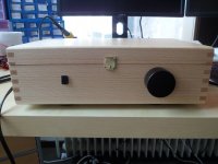
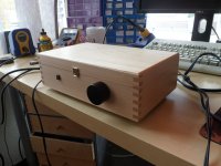
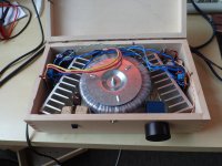
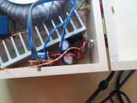
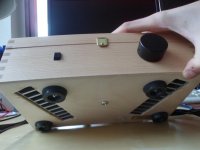
So, it's done! Here's the pics I promised.
There's still something weird with the left channel, it has a DC of 18mV on the speaker outlets, where the right channel has only 2mV. I don't hear anything weird, and I think 18mV is in the doesn't-break-your-speaker range, but it's suspect so perhaps I have to change some components there. During the building there was an incident where I had the amp built without a case, and a friend bumped it and shorted the speaker terminals while it was playing. I had the series lamp connected, and it flashed bright for a while as my friend realised something was amiss and turned it off, perhaps that broke something?
The amp is playing through my cheap burn in speakers, it's already sounding quite nice, it has a tight base and the sound is clear.
Attachments
Last edited:
The bulb tester does not protect AFTER it is powered up.
The charge/Energy in the smoothing capacitors will be sufficient to damage during an incident.
The bulb tester protects during power up, if you choose the correct wattage. Start low, rather than high.
The charge/Energy in the smoothing capacitors will be sufficient to damage during an incident.
The bulb tester protects during power up, if you choose the correct wattage. Start low, rather than high.
So you're saying there's a good chance something broke? What's the most likely, the chipamp itself?
Possibly.
The offset is not bad @ 18mV.
But that might indicate that some junctions have been overly stressed and could have a much shortened lifetime.
How much does the offset change from a cold start, to warm, to hot?
Can the offset be trimmed by adjusting the input resistors?
Might be safer to fit DC detection and isolation of speaker.
After being on for a few hours it dropped to around 6mV.
If it's really a bit dodgy, wouldn't it be easier to just replace the chip instead of adding DC detection, or is that something really simple? Speaker isolation would be output transformers right?
If it's really a bit dodgy, wouldn't it be easier to just replace the chip instead of adding DC detection, or is that something really simple? Speaker isolation would be output transformers right?
I doubt that's an issue - my non sparked chips give a bit more than 10 mV. Mismatched impedances I guess.
that gradual drop could be reducing leakage current through a capacitor that is reforming in circuit.After being on for a few hours it dropped to around 6mV.
If it's really a bit dodgy, wouldn't it be easier to just replace the chip instead of adding DC detection, or is that something really simple? Speaker isolation would be output transformers right?
The pulse current may have reverse charged a capacitor and temporarily increased leakage.
You might like to read this thread, paticularly from #11 which makes reference to Bob Cordell's book and notes on controlling DC offset with these related chipamps.So, it's done! Here's the pics I promised.....There's still something weird with the left channel, it has a DC of 18mV on the speaker outlets, where the right channel has only 2mV.....
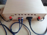
I like the cute box in your build but you may need to increase the number of holes in the rear of the lid to ensure adequate and even airflow right across the width of the box. You need this for both cool running chips and electrolytic capacitors but also to prevent heat damage to the glues and finish of the case, over time.
- Status
- Not open for further replies.
- Home
- Amplifiers
- Solid State
- How do I find out which amp I should build?