Hmm..
You say it blows a 2A fuse with no connections of the secondary windings at all?
This suggests the primary winding or wires to it are shorted. Remove the transformer and measure the resitance of the primary winding, checking to see if there is continuity to any secondary windings too, and post please. I have doubts about the wiring or rather, the identification of the windings. Would you also mind telling us how the windings are identified, post a clear pic etc?
Some universal transformers have split primaries, to allow 115 or 230V supplies. Is it a single primary winding? Is it, a conventional (square shaped) E-I transformer or toroid? What power (VA rating) is it?
The CFL type lamps are unsuitable for incandescent (wire filament) requirement. Since we in Oz started that crazy CFL trend some years ago and then banned them too, so now we use a pointless 20% energy saving halogen bulb that produces 25% less light than claimed by the manufacturers! However, they are incandescent and should operate well enough at the same wattage rating as an ordinary bulb. I've kept a few old types for the purpose but please, don't use standard film resistors on the primary (mains) side. The voltage exceeds their ratings and their connections will be unsafe if exposed.
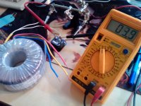
I hope this image is clear enough. So I am measuring about 4 ohm resistance between the primary leads, they are currently soldered to the mains socket, it doesn't have a fuse in it and it's not connected to a wall socket.
I measured .5 ohm between the red and yellow leads, and .5 ohm between the blue and grey leads.
I am fairly certain I got the windings right, as I have a brochure that came with the transformer that explains the lead colors with a little diagram.
So, yes it blows a fuse if I connect it without anything connected to the secondary windings, just the transformer to the mains.
Attachments
Ok, your readings are about correct for a 160VA toroidal transformer, as I just checked a 300VA version I had nearby with a 230V primary of 3.3R and 30V secondaries of 0.4R - consistent with the higher current rating ). I also asked you to check for any reading from primary to secondary windings, though of course, there should be none.
The label should also indicate the winding pairs and (hopefully) indicate the "sense" as described earlier. It's good that you have a brochure, though. For interest, the colour code of the secondaries is the same as yours since this is a standard. It is also becoming common to incorporate a thermal fuse in toroidal transformers too and this protects the tranformer from overheating but probably not from dead shorts. If this type of overload has occurred and either the fuse or just the winding has overloaded, it will usually just burn out to an open circuit. This would mean your resistance reading would be infinite or perhaps low, in the case of a short. You have normal resistance, so I doubt there's any problem.
I'd say the the problem may be with the fuse rating. Make up your bulb tester and try again, even with no fuse. Try to work with a little more safety than the loose mains socket and leads shown in your pic. Be a bit more safety conscious and even buy some thick, insulated clip leads sold for temporary connections like these: (Ebay NL ref. 160566693256 ) Still take great care as they are not rated for use at mains voltage -very little bench equipment actually is, so safety is still down to you.
Dont hesitate to return if you have your own doubts about the bulb tester but there are plenty of guides for DIYs here and on other sites. I prefer building one into a 2-way adapter socket and just plugging in a table lamp to make it work but others prefer a mains junction box or just a simple, ceiling mounted light socket screwed to a piece of timber. It is your choice but ensure that the connections are tightly screwed and securely covered with insulating material.
There won't be a huge inrush with this little transformer, but it may be enough to blow a 2A fast fuse. Have you tried a slow blow or higher rated fuse? I suspect that when you hook up with a bulb tester as Ian suggests you'll find the bulb lights briefly then dims, and you will have nice steady output.
There is often a conflict between having a fuse rated closely enough to the transformer's rating and high enough not to blow with the inrush. I've found with 500VA transformers using a CL60 to limit inrush current I still need a 6A slow (120 VAC mains) blow to not have random inrush inspired fuse blows. The good news is if something goes south, the usual result is the current goes high enough to blow any fuse that you may have long before burning up the transformer.
There is often a conflict between having a fuse rated closely enough to the transformer's rating and high enough not to blow with the inrush. I've found with 500VA transformers using a CL60 to limit inrush current I still need a 6A slow (120 VAC mains) blow to not have random inrush inspired fuse blows. The good news is if something goes south, the usual result is the current goes high enough to blow any fuse that you may have long before burning up the transformer.
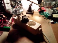
Hey I thought I'd share some more progress, I built the bulb tester!
It's made out of a regular multiple socket, a big power switch and a halogen lamp fitting + lamp. All hooked up in series, I tested it out, and the halogen shines bright when the socket is short circuited, and is off when it's disconnected so it seems I wired it up right.
edit: so to be clear to anyone trying to copy this. The lamp is not actually in the socket like a regular lamp would be, the wires go _through_ the holes into the multiple socket, one connects with the left rail, the other with the blue wire that went into the multiple socket from the wall socket, with the switch in between. The blue wire in the multiple socket does _not_ connect to the left rail directly like it would normally.
Attachments
Last edited:
'Good to see some success but I worry about your concept of safe working with mains voltage. Is that bare connections to the rocker switch we see in your Pic?....It's made out of a regular multiple socket, a big power switch and a halogen lamp fitting + lamp. All hooked up in series,....The lamp is not actually in the socket like a regular lamp would be, the wires go _through_ the holes into the multiple socket, one connects with the left rail, the other with the blue wire that went into the multiple socket from the wall socket, with the switch in between. The blue wire in the multiple socket does _not_ connect to the left rail directly like it would normally.
Last edited:
Hi Ian,
I'm not sure what you're seeing in the pic. All wires are _inside_ the multiple socket, the wires are sleeved except for the last part where they're soldered to the rocker, and the rocker has been taped all around into the socket. There's no wires visible from the outside.
The only bare copper you see is the grounding of the sockets.
Thanks for the clarification. Have you had the opportunity to test the transformer alone on this power source, without a fuse? That is a 230V halogen bulb, I presume, because low voltage types are not suitable. Here in Oz, halogen energy saver lamps are enclosed in the old familiar glass bulb format, so I'm curious too.
If correct for mains line voltage, were there problems with the transformer secondary winding AC voltages?
If correct for mains line voltage, were there problems with the transformer secondary winding AC voltages?
Hi guys!
Sorry for the long quiet period. I got an arduino and did a little project with that which was succesful and now I've returned to work on the amp project.
So now I had the bulb tester, using a 230v halogen bulb indeed, I used it to verify the transformer was still working and it was. Then I connected the rectifier circuit and tested that, also worked. I took care to mark the + and the - side this time 😉 Then I connected the amp and this time less than 100mV DC!
So great success! You guys probably were right, and I had a loose connection to the rectifier somewhere, because now it's going great and I didn't change anything but resolder the rectifier to the amp.
The next step I took was connecting it to a throwaway speaker. I picked one up at the recycling store for just this purpose, an 8ohm 10W speaker. I connected an old iPod to the input and turned the volume way down low and turned the amp on.
Now I expected it to make a lot of noise, since it's just a 10W speaker and I have no volume pot yet, but it actually didn't. Even with the iPod cranked way up the speaker was very soft. On the upside, it was actually good sounding music that was coming out of the speaker! So if anything at all, I made something that amplifies sound without (much) distortion!
So my question for today:
Is it normal that it didn't go very loud? I figure it's one of these three options:
a) The volume knob will somehow fix it
b) I bought a broken speaker/wrong speaker
c) Something is still not connected very well
Thanks for the support so far guys, I couldn't have done it without you 😀
Alright, I'm a bit stumped now. I tried a different speaker, same thing. I tried a different input source (my phone) also very low volume. I also tried the amp without the bulb tester.
Could it be this amp needs a preamp to amplify an ipod? All the solder joints seem good.
Could it be this amp needs a preamp to amplify an ipod? All the solder joints seem good.
Hi, It's great to "hear" some success, isn't it?
You could clear up any doubts about the speaker by looking at the driver unit itself. An 8 ohm speaker driver should measure around 6.5 ohms DC resistance or it will be marked appropriately anyway. If the speaker you refer to is complete in a box, isolate the bass driver connections and measure it alone (ie. disconnected) since other drivers like midrange, tweeter and the crossover network will affect the measurement.
R1,R2 in the Audiosector building guide schematic, form a voltage divider that may affect the input signal level and thus output volume level.
R3,RF form another divider that determines the feedback: output ratio and thus the voltage gain of the amplifier.
Recheck that the values are correct and in the right positions or it sure will be quiet!
If your source was an MP3 player, you may need to increase R1 to 1k or greater as the low impedance of a headphone output may affect the input. The voltage level though, should be adequate to drive the amplifier directly. I would also look around for a preamplifier or the line output of a conventional power amp. - as long as there is a volume control, to avoid destruction at what would otherwise be maximum power.
Needless to say, recheck the rail voltages but note that the bulb tester, if still in place, limits current and thus power. Yes, it will be quiet and sound awful this way but I guess you discovered this already.
Last edited:
Could be b, c or nothing at all. Try downloading a signal generator application and feeding your amp a straight 60 Hz. sine wave. Set the level to 1V. With NO SPEAKER connected apply this signal to the amp and measure the output. If over 25V things are as they should be, it's just that the average level coming from your ipod is low and you may need a bit of gain to go along with your volume pot. If closer to 1V than 25, check your feedback resistor values.
Hi, It's great to "hear" some success, isn't it?
Yes definitely 😀
If your source was an MP3 player, you may need to increase R1 to 1k or greater as the low impedance of a headphone output may affect the input. The voltage level though, should be adequate to drive the amplifier directly. I would also look around for a preamplifier or the line output of a conventional power amp. - as long as there is a volume control, to avoid destruction at what would otherwise be maximum power.
I don't fully understand that. I thought maybe the value was too high, dampening out the value, but you're saying it could actually be too low? The project is in boxes right now because when I'm not soldering the desk is my work desk, but I suspect I soldered a 200R in there.
I've never fully understood impedance. I sort of get the analogy where waves can sort of 'reflect' with an impedance mismatch, but I have no clue to the other electrical effects that could happen. I should definitely read up on that.
So I think I'm very close to cracking this, and I hope the next time I break out the soldering tools I'll build the second channel. I'm going to look for some more serious heatsink and browsing for a potmeter.
What do you guys think of this one? It's the only one Farnell has in stock in the UK (which ships for free to NL). I think it's pretty expensive, but I've heard these things go for a lot more and it's probably not wise to skimp on it (I've restored some vintage amps, and know what happens to crappy once).
RK27112B0A0B - ALPS - POTENTIOMETER, 50K, WITH CENTRE | Farnell Nederland
If it's sucky I'll have to find a more high end dealer in the NL somewhere, hopefully before christmas so I can work on the case with my dad in his workshop.
Thanks for all the help!
Hi.
Alps RK27 pots are great products, probably the best conventional types readily available. You don't need the type with a centre tap though, unless you want to design and add a "loudness" feature (something that older integrated amplifiers used to automatically boost bass at lower volume levels). I'm sure that price can be bettered though, even in Europe. e.g. Familygate, Ebay ref. 350937325846.
The input impedance of the amplifier is usually designed to be high, in the order of 20k but this is actually defined by the series of resistors R1 + (R2 in parallel with the actual internal chip impedance). You may not need an input capacitor using an MP3 player source but add the 4.7uF input cap before R1 anyway, to reject any accidental DC from the input, whilst you are experimenting. RF interference is also likely with this simple design but let's cross that bridge when we come to it. 😉
Adding a volume control won't increase the input level though - it can only reduce the output to a proportion of the input so you still need to recheck your resistor values to make sure you aren't throwing signal away by using the wrong values. Also, check that you have a proper ground connection for the input lead, socket etc. This greatly affects the signal and I've seen guys get this wrong, such that they had very weak or no signal at all.😕
Is the center tap detrimental to something or is it just an extra feature? The ebay one has $10 shipping costs, and I don't see anything else in his stock that I need so it still comes out more expensive than Farnell.
There are plenty of other sources such as this Ebay one - 320693498438 for US $15 +3 - keep looking. Funny, I just checked Farnell- Nederland site and only found a 20K ALPS RK27 log. taper, in stock at a price of 35 Euros! 😱 Perhaps you have better access to the listings or yours is an old reference.
In any case, the item you referred to has a centre detent or "click", not a tapping as I mistakenly assumed, so whilst it has a logarithmic taper but isn't tapped, the detent suggests it is meant for use as a balance control and the rotation characteristic may not suit use as a volume control. If the datasheet is correct, the midpoint will also be half the resistance value and that won't be suitable at all. If you pay a lot of money for a volume control, it should at least be right for the job. Generally, Ebay sellers only offer standard volume control types - if not, they usually say so.
In any case, the item you referred to has a centre detent or "click", not a tapping as I mistakenly assumed, so whilst it has a logarithmic taper but isn't tapped, the detent suggests it is meant for use as a balance control and the rotation characteristic may not suit use as a volume control. If the datasheet is correct, the midpoint will also be half the resistance value and that won't be suitable at all. If you pay a lot of money for a volume control, it should at least be right for the job. Generally, Ebay sellers only offer standard volume control types - if not, they usually say so.
Last edited:
I found it at conrad for 16 euro. If I order 9 euro more they'll send it for free. They seem to have more stuff I need so I'll browse around for a bit. If I order at Conrad there's a chance they'll deliver it friday, which would be excellent.
Stereo potmeter RK27112 50 kOhm in de Conrad online shop
Stereo potmeter RK27112 50 kOhm in de Conrad online shop
- Status
- Not open for further replies.
- Home
- Amplifiers
- Solid State
- How do I find out which amp I should build?